
LDI ROW Non-Contact Oil Detector X2 Integration Guide
Real-Time Oil Detection in Water
The LDI ROW Aluminum Oil Detector is an autonomous non-contact sensor for the detection of oil on water in industrial and environmental applications. The sensors are compatible with the NexSens X-Series data loggers via the Modbus-RTU protocol and the RS-485 sensor interface. Parameter data is transmitted, in real-time, at a user-specified interval (e.g., 10 minutes) to the NexSens WQData LIVE Web Datacenter. There, data is stored on customizable dashboards with statistics and graphical interfaces for each parameter. Users can download and send data reports via Email, FTP, or an API. Below is information on the settings and wiring required to integrate LDI ROW Aluminum Oil Detectors with NexSens X-Series data loggers.

Figure 1: LDI ROW Aluminum Oil Detector integration with NexSens X-Series data loggers.
Compatible Models
The LDI-ROW Oil Detector uses a pulsed UV LED light beam to excite oil molecules in the monitored water area to induce fluorescence. The return signal is collected and analyzed immediately to determine if oil is present. The sensor comes in various housings for different applications. The alunimun model provides the most versatility to be used on many applications. The stainless steel model is used in tough environments when a wide range of oils is possible. The Exd model is fully certified according to ATEX/IECEx for installation in Zone 1, explosive areas.
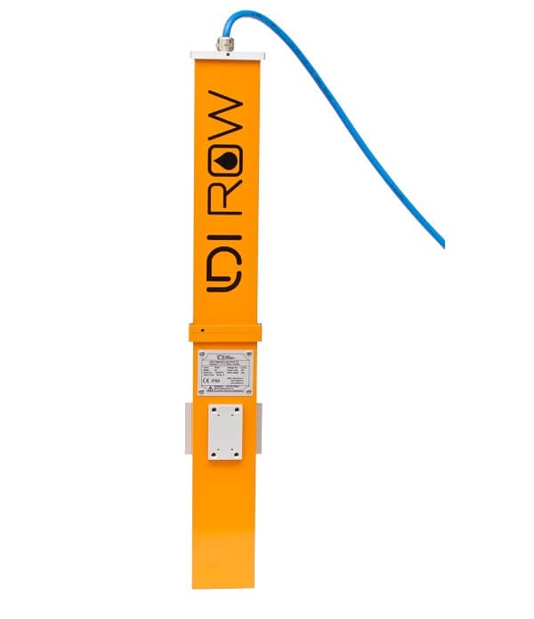
Figure 2: LDI Row Aluminum Model |
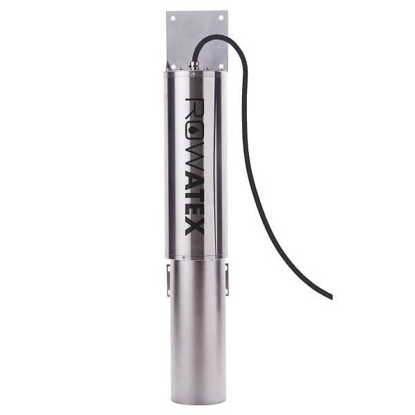
Figure 3: LDI Row Stainless-Steel Model |

Figure 4: LDI Row Exd Model |
LDI-ROW Integration
1. Wiring
In nearly all applications involving NexSens integration, a connectorized UW8 plug will be added to the sensor cable. However, other applications may require a UW8 to flying lead cable utilized for wiring the sensor and cable into an external junction box. The following table provides information for both applications.
| NexSens UW8 Plug Pin | NexSens UW8-FLx Wire Color* | Signal | LDI-ROW Wire Number |
| 1 | Orange | RS-232 Tx | — |
| 2 | Black | Ground | 2 |
| 3 | Yellow | RS-232 Rx | — |
| 5 | Red | 12V Power | 1 |
| 6 | Brown | SDI-12 | — |
| 7 | Blue | RS-485 B | 4 |
| 8 | Green | RS-485 A | 3 |
*NexSens UW Plug to Flying Lead Cable
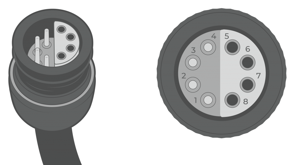
Figure 5: NexSens UW8 Plug pin numbers.
2. Adjust Sensor Settings
The LDI-ROW sensor can communicate with an X-Series data logger via RS-485 with the default settings. However, to improve measurement accuracy and response, follow the settings changes below.
Note: More detailed information can be reviewed in section 3 of the LDI-ROW manual that is included on the USB flash drive.
- Use the included USB flash drive to download the LDI-ROW Configurator Software.
- Connect to the device using the included configuration cable, or if a NexSens connector has been installed, use a UW-USB-485R-DC.
- Once connected, review the device parameters to ensure they are set up correctly for the application.

Figure 6: LDI-ROW Device Parameters
3. Automatic Sensor Detection
The user must create a Modbus script through the NexSens CONNECT software to communicate and gather measurements from the sensor. Follow the link below to review the process for creating a Generic Modbus script through the CONNECT Software:
Script Outline
The image below outlines the default settings that should be set for a Modbus script. The settings include the default communication for the sensor (i.e., RS-485 connect, 57600 baud, & N81 frame). Setting the port to P0 (full power) is not recommended for solar-powered systems, as the LDI-ROW consumes ~167 mA while running. Port P1 or P2 and switch power should be selected to conserve battery power. The warmup time is dependent on the sensor’s alarm delay time and must be at least 10 seconds longer than the alarm delay time.
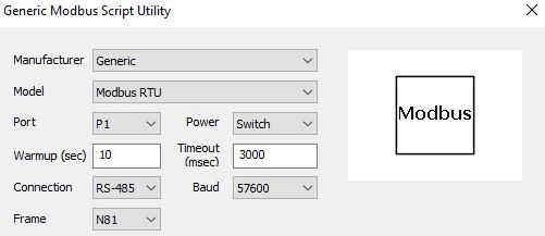
Figure 7: Modbus script general settings. |
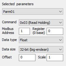
Figure 8: Example parameter settings for “Signal Value”. |
Note: All parameters are read using command 0x03 (Read Holding). Ensure that the Modbus address matches the address set on the sensor.
| CONNECT Parameter | LDI-ROW Parameter | Data Type | Data Size | Starting Register | Description |
| Parm01 | Signal Value | Float | 32-bit (big-endean) | 0 | Average signal over the latest batch of measurements by ROW. Reflects the fluorescent signal intensity |
| Parm02 | Background Value | Float | 32-bit (big-endean) | 2 | Average background over the latest batch of measurements by ROW. |
| Parm03 | Simple State | Signed Integer | 16-bit | 4 | A simplified device state -0: Online and OK. The device is functioning normally, and alarm has not been raised -10: Alarm. There is an oil spill detected by the device -100:Service Required. The LED light intensity has dropped to the point where the device is no longer operational and should be serviced by LDI. |
| Parm04 | Data Counter | Signed Integer | 16-bit | 5 | It increments every time ROW reads and processes another batch of data and updates the signal, background and state. This value can go up to 65535, and then begins again from zero. |
Run the Sensor Detection
Once the script is created, transfer and enable it on the data logger.
After the script is enabled, run a sensor detection to program the sensor onto the logger.
Read Sensor Configuration – Confirm Sensor Detection
After ~5-10 minutes, read the sensor configuration to confirm the sensors have been detected on the data logger. Thoroughly review the parameter list to ensure all parameters are accounted for and are measured in the desired units. Let the unit gather a few readings to confirm accurate and reasonable parameter data.
4. Setting up WQData LIVE
Once an X-Series data logger has finished a new sensor detection, it will automatically push the sensor configuration to the WQData LIVE web data center. Follow the three articles below to create a WQData LIVE account and a project/site. Then add the data logger to the project using the included claim code.
- Create a WQData LIVE Account
- Create a Project on WQData LIVE
- Add a Data Logger to a Project on WQData LIVE
Setting a WQData LIVE Alarm
It is recommended to set two alarms or quick alerts based on the output value of parameter 3 (Simple State). These will immediately alert you to oil detection or sensor issues. One alarm/alert should trigger at a value of 10 and the other at a value of 100 (see the description in the script outline above).
- Setting Quick Alerts
- Quick Alerts can be used with the Basic tier of WQData LIVE
- Setting Alarms
- Alarms can be used with the Advanced tier of WQData LIVE
Real-Time System Application
Real-time oil detection from the LDI-ROW Oil Detector is useful in various environmental monitoring applications.
Applicable Systems
Discover applicable uses for the LDI-ROW Oil Detector.