
Generate Generic Modbus Script
Modbus sensors not already listed in the X2 sensor script library can be configured to communicate with the X2 by generating a generic Modbus script.
- Connect the X2 logger to a PC and launch the CONNECT software. Test connection by reading the RTC clock of the logger in the CONFIG tab.
- On the CONFIG tab, click the drop-down arrow to the right of the Create Script button and select Generic Modbus.
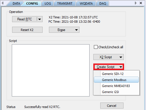
Figure 1: Create generic Modbus script.
- The Script Utility menu will appear.
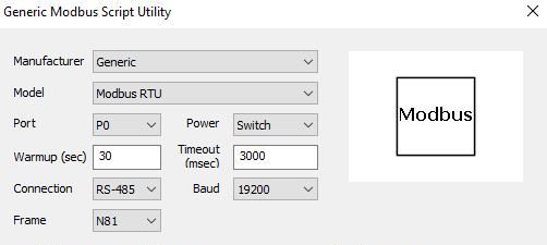
Figure 2: Modbus Script Utility menu.
Modbus Script Specifications
The generic Modbus script must include the following specifications:
- Manufacturer – By default, this parameter will be Generic. However, a list of common manufacturers and their respective sensors are also available. Specifying the manufacturer and sensor name has the following effects over generic:
-
- The available parameter list shows only those that typically apply to the selected sensor (select Show All to remove this filter).
- The sensor’s default parameter output automatically appears in the Selected Parameters column (although it is still possible to manually edit the list).
- The X2 posts the sensor model name to WQData LIVE instead of showing as a Generic sensor type.
-
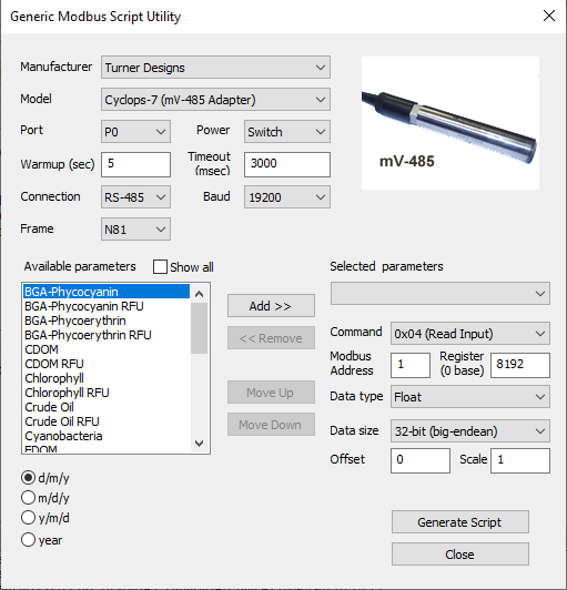
Figure 3: Example with Turner Designs Cyclops-7 pre-selected for the manufacturer and model.
- Port – Specify the X2 sensor port the device will be connected to (P0, P1, or P2).
- Power – Select the power type required for the sensor from the following:
- Switch – turns on power to the listed sensor port at a specified period of time ahead of each scheduled reading. The sensor powers off once the X2 collects data for the reading. The Warmup field determines how long the sensor will be powered in advance of each reading.
- For most sensors, 30 seconds will be sufficient, but check with the manufacturer specifications. Occasionally, sensors require longer warmup periods to reach their peak accuracy rating.
- In general, sensors deployed with internal batteries should not use switch power. In between readings, when the X2 port power is off, the internal sensor batteries will drain and this can lead to communication issues once they are exhausted. Either remove batteries or select the Continuous power option.
- Continuous – the specified X2 sensor port will have power applied constantly. This is typically less power efficient, but depending on the sensor type may be a requirement (ex. weather sensors running continuous rain/wind averaging calculations).
- None – the listed X2 sensor port will not receive power and internal batteries will power the sensor.
- Switch – turns on power to the listed sensor port at a specified period of time ahead of each scheduled reading. The sensor powers off once the X2 collects data for the reading. The Warmup field determines how long the sensor will be powered in advance of each reading.
- Baud – Choose the baud rate utilized by the sensor.
- Frame – Select the communication frame used by the sensor (parity, #data bits, #stop bits).
- Available Parameters – Select the parameters which the sensor will report one at a time, then click Add for each one. Choose the correct units for each parameter below the parameter list.
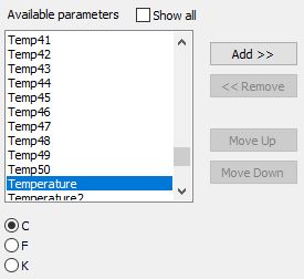
Figure 4: Available parameters list.
- Click the drop-down menu to choose a Selected parameter to edit. Update the following for each parameter:
- Command – Enter the Modbus command that the X2 will send to the sensor for reading measurements.
- Modbus Address – Enter the Modbus address for the sensor and select the starting register for the parameter data.
- Register – Pick the register type used to query the selected parameter from the Command list.
- Data Type & Data Size – Specify the data format including type and size.
- [Optional] Offset – Enter an offset and scale. Most often, these values should be left at their defaults of 0 and 1, respectively.
- Repeat the process until all selected parameters have the proper register and data type information entered.
- Review each parameter to ensure all of the information displays correctly.
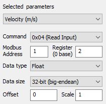
Figure 5: Parameter 1 settings review. |
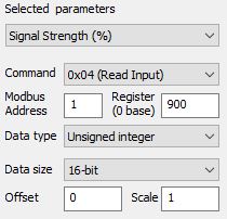
Figure 6: Parameter 2 settings review. |
- Once outlining the script settings, click Generate Script in the bottom right corner of the menu, assign a script number, and click OK.
- If creating multiple generic scripts for the X2, assign a unique value to each.
- If making modifications to an existing generic script, assign the same script number to overwrite the original.
- CONNECT saves the generic script in the CONNECT software folder shown in Figure 7.
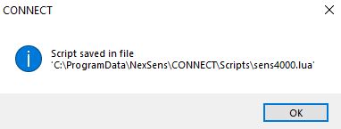
Figure 7: Successfully generated script.
- Follow the Configure Sensor Scripts document to:
- Transfer the new script to the X2 (demonstrated in the Add/Update Sensor Scripts section).
- Read the existing X2 script list (shown in the Show Enabled Sensors section).
- Enable the custom script to run during sensor detection (demonstrated in the Modify Sensor Detection List section).
- Connect all sensors, apply 12V power and run sensor detection in CONNECT (alternatively, by queuing the Sensor (Auto)Detection command from WQData LIVE or through the X2 embedded web).
- Once receiving the detection command, the X2 will run the generic script. As long as the sensor responds according to the script settings, the X2 will identify it, and data collection and posting to WQData LIVE will begin.