Aanderaa Doppler Current Profiler X-Series Integration Guide
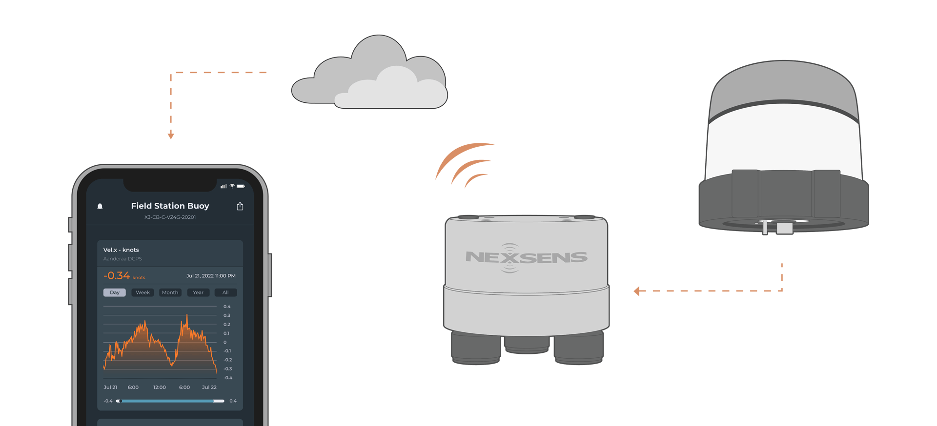
The Aanderaa Doppler Current Profiler Sensor (DCPS) is a medium-range, 600kHz current profiler for deployment on fixed or moving platforms. The DCPS is compatible with NexSens X-Series data loggers using RS-232 communication.
Sensor Setup
Before the sensor can be deployed, follow the manufacturer’s guidelines to complete setup. For pairing with NexSens X-Series data loggers, ensure the following settings are enabled in the Terminal Protocol:
- Enable Polled Mode
- Disable Text
- Enable Decimal format
Note: NexSens X-Series loggers support a maximum of 179 parameters per sensor and 200 parameters for the overall system, so users should take care not to exceed these limits. Using the default Simple Output, the sensor outputs 23 default parameters plus 5 parameters per cell. Therefore, the following calculation should be performed to ensure the system does not exceed the limit.
Total Parameters = 23 + (5 x Number of Cells)
Connecting with X-Series Loggers
Next, the Aandera DCPS will need to be set up for the X-Series logger using CONNECT software. Before proceeding, set up the project in WQData LIVE.
- Connect the DCPS using the supplied cable to one of the open sensor ports on the logger and note the port number.
- Plug the X3 into the USB port of the computer and power it on with the AC power cable.
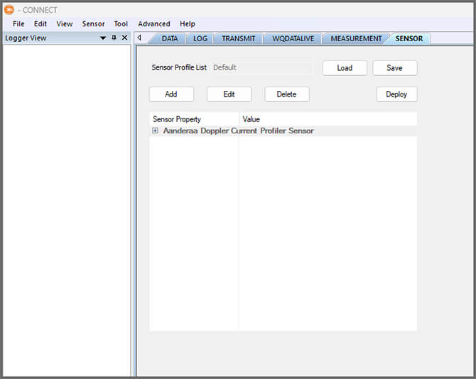
- Open CONNECT and select the SENSOR tab.
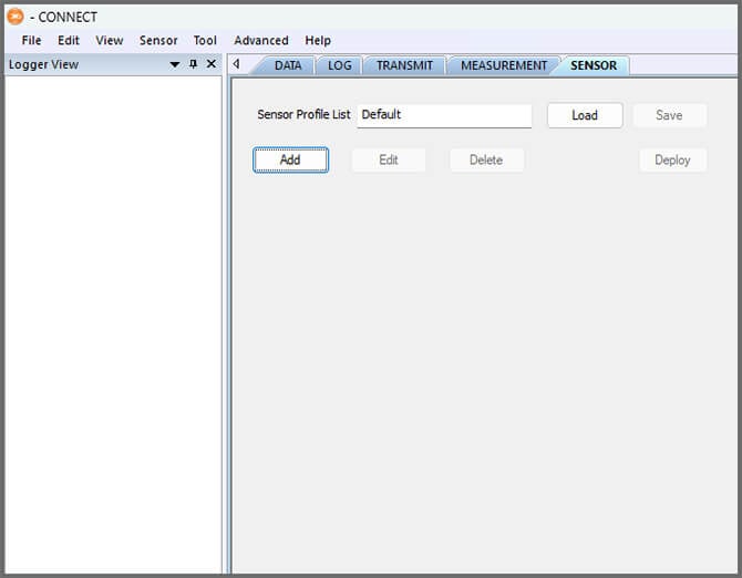
- Click Add and select Aandera from the Manufacturer drop-down. Then select the appropriate model.
- Select the port number and Connection.
- Select either Continuous or Switch in the Power drop-down.
- Continuous is recommended.
- Set the Num Cell as needed. It must match the num cell set in the Aandera software.
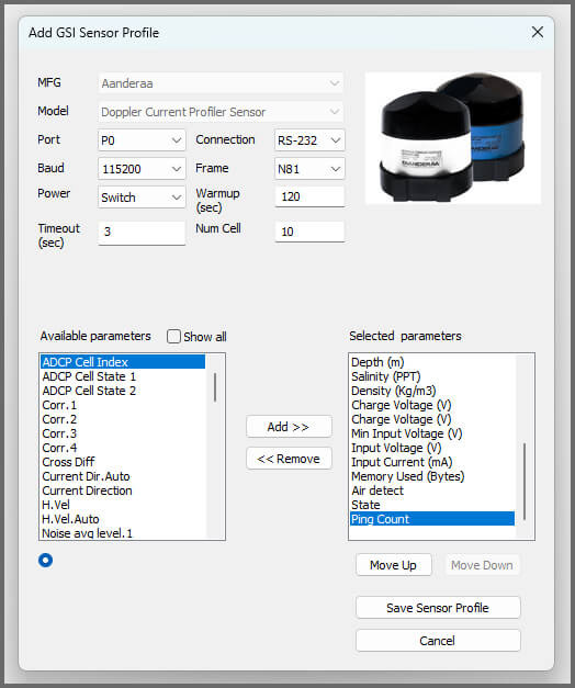
- Select Save Sensor Profile.
- Complete the setup for all other sensors, and then click Save.
- Name the Sensor Profile List and select Ok.

- Complete system setup by clicking Deploy.
- Confirm that data is being transferred to WQData LIVE at the next interval (default is 10 minutes).
Mounting
Deployment setups will vary based on the platform, application, and site location. For general buoy mounting instructions, see below.
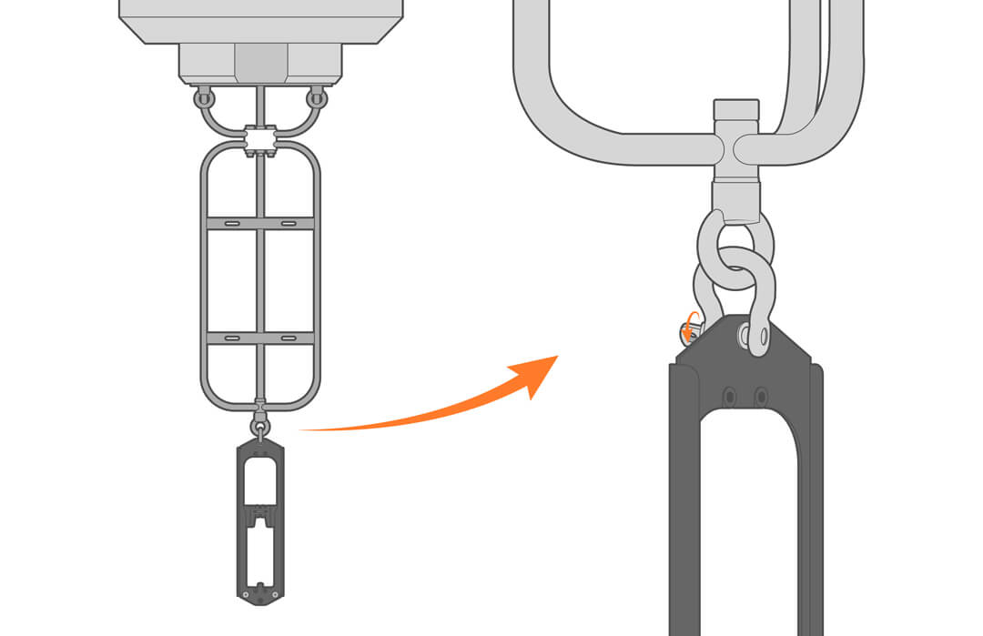
Buoy-Based Deployments
The Aandera DCPS arrives already in its harness and will simply need to be attached to the bottom of the NexSens buoy’s instrument cage using a shackle.