
Generate a Generic GSI Script
Sensors utilizing serial communication that are not already listed in the X2 sensor script library can be configured to communicate with the X2 by generating a Generic General Serial Interface (GSI) script.
Note: The X2 data logger only supports the RS-232 and RS-485 serial communication protocols. This utility requires a CONNECT firmware version of V2.22.7.2 or higher.
GSI Script Utility
- Connect the X2 logger to a PC and launch the CONNECT software. Test connection by reading the RTC clock of the logger in the CONFIG tab.
- On the CONFIG tab, click the drop down arrow to the right of the Create Script button and select Generic GSI.

Figure 1: Create a generic GSI script.
- The GSI Script Utility menu will appear.
Sensor-Specific GSI Script
The manufacturer and model of common sensors using GSI communication are available within the GSI script utility. By selecting the manufacturer and model of the sensor, the utility will automatically generate a list of known parameters measured by the device. If the manufacturer and model for the sensor are available, skip to the GSI Script Specifications section to begin creating a GSI script.
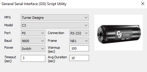
Figure 2: Turner Designs C3 Submerisble Fluorometer selection.
Generic GSI Script (Requires CONNECT software version of V3.23.3.23 or higher)
If the sensor is not available within the script utility, contact NexSens Technology at (888)-426-2151 or at [email protected] to request the sensor addition or review the process below to create a Generic GSI script.
Sensors communicating via GSI can be separated into different categories based on their serial output. The first category is defined by the delimitation for the sensor output:
- Comma delimited (CSV)
- Space/tab delimited
The second category is whether the sensor requires a command to start outputting data or gathering a reading. Sensors can be separated into the following categories:
- No command: when powered on, the sensor begins to output data one line at a time continuously.
- Single command: when powered on, the sensor is in an idle state. The sensor begins outputting data continuously upon receiving a single command.
- Multiple commands: when powered on, the sensor is in an idle state. The sensor outputs a single data line upon receiving a read command.
The generic GSI script only works with sensors that output uniform data in table format as defined below:
- Each line contains 1 or more parameters.
- Each column contains exactly 1 parameter.
- The same column holds data from the same parameter.
- A comma, space, or tab separates multiple parameters on the same line.
Below are examples of uniform and non-uniform data output. Only the uniform data output is compatible with the GSI script utility.
|
|
The Generic option in the GSI script utility allows the user to interface with any GSI sensor as long as they understand the data output from the sensor. Refer to the sensor manual or view the output in a terminal emulator to determine the categories to which the sensor belongs. If the sensor requires a “Start Measurement” or “Get Data” command, enter the command in the Start Meas Cmd and/or Get Data Cmd boxes within the script utility, respectively. Before generating the script, review the additional script requirements in the Sensor-Specific GSI Script Specifications section below.
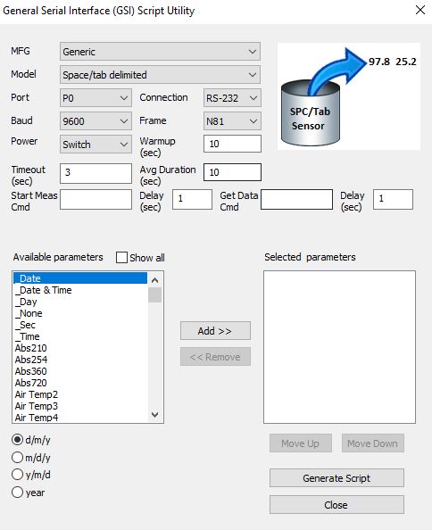
Figure 3: Generic GSI script generation.
GSI Script Specifications
- Manufacturer and Model – Choose the appropriate manufacturer and model of the sensor to automatically generate a list of known parameters measured by the device.
- Port – Specify the X2 sensor port the device will be connected to (P0, P1, or P2).
- Baud – Choose the baud rate utilized by the sensor. CONNECT will automatically display the manufacturer’s default baud rate.
- Power – Select the power type required for the sensor.
- Switch – turns on power to the listed sensor port at a specified period of time ahead of each scheduled reading. Power is turned off once the data for the reading has been collected by the X2. The Warmup field determines how long the sensor will be powered in advance of each reading.
- For most sensors, 30 seconds will be sufficient, but check with the manufacturer specifications. Occasionally, sensors require longer warmup periods to reach their peak accuracy rating.
- In general, sensors deployed with internal batteries should not use switch power. In between readings, when the X2 port power is off, the internal sensor batteries will drain and this can lead to communication issues once they are exhausted. Either remove batteries or select the Continuous power option.
- Continuous – the specified X2 sensor port will have power applied constantly. This is typically less power efficient, but depending on the sensor type can be a requirement (ex. weather sensors running continuous rain/wind averaging calculations).
- None – the listed X2 sensor port will not receive power and internal batteries will power the sensor.
- Switch – turns on power to the listed sensor port at a specified period of time ahead of each scheduled reading. Power is turned off once the data for the reading has been collected by the X2. The Warmup field determines how long the sensor will be powered in advance of each reading.
- Timeout – Select the timeout time recommended by the manufacturer.
- Connection – Choose the type of serial communication (RS-232 or RS-485) utilized by the sensor.
- Frame – Select the communication frame used by the sensor (parity, #data bits, #stop bits). CONNECT will automatically display the manufacturer’s default frame.
- Warmup – Input the warmup recommended by the manufacturer. CONNECT will automatically display the manufacturer’s default warmup time.
- Average Duration – The CONNECT script will average measurements over a certain duration of time. Since many sensors communicate through serial communication output at 1Hz, a 10-second average duration would provide an average of 10 overall measurements.
- Available Parameters – Construct the appropriate parameter output list for the sensor by assigning parameters to the Selected Parameters column using the Add/Remove/Move Up/Move Down buttons.
- The total number and ordering of parameters for the script must match the parameter output for the sensor.
- If the sensor outputs a diagnostic or undesirable parameter as a part of its measurement command, it can be omitted from logging to the X2. Substitute the _None parameter into its position on the Selected Parameters list.
Sensor Detection
- Once outlining the script settings, click Generate Script in the bottom right corner of the menu, assign a script number and click OK.
- If creating multiple generic scripts for the X2, assign a unique value to each.
- If making modifications to an existing generic script, assign the same script number to overwrite the original.
- CONNECT saves the generic script in the CONNECT software folder shown in Figure 4.
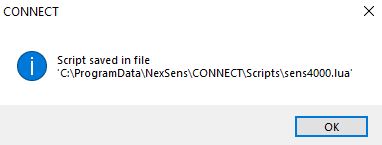
Figure 4: Successfully generated script.
- Follow the Configure Sensor Scripts document to:
- Transfer the new script to the X2 (demonstrated in the Add/Update Sensor Scripts section).
- Read the existing X2 script list (shown in the Show Enabled Sensors section).
- Enable the custom script to run during sensor detection (demonstrated in the Modify Sensor Detection List section).
- Connect all sensors, apply 12V power, and run sensor detection in CONNECT (alternatively, by queuing the Sensor (Auto)Detection command from WQData LIVE or through the X2 embedded web).
- Once receiving the detection command, the X2 will run the generic script. As long as the sensor responds according to the script settings, the X2 will identify it, and data collection and posting to WQData LIVE will begin.