
NexSens TS210 Temperature String User Guide
Real-Time Water Temperature Measurements
The NexSens TS210 Thermistor String provides high-precision temperature measurements for profiling in lakes, streams and coastal waters. It features an integral titanium thermistor secured and epoxied in a protective housing for underwater deployments. TS210 strings integrate with NexSens X-Series data loggers using the Modbus communication protocol and RS-485 sensor interface. A pre-defined script on NexSens X-Series data loggers is available to detect, log and transmit the temperature data. Parameter data is transmitted, in real-time, at a user-specified interval (e.g., 10 minutes) to the NexSens WQData LIVE web data center. There, data is stored on customizable dashboards with available statistics, graphical interfaces and the ability to download and send data reports via Email, FTP or an API. Below is information on the settings and wiring required to integrate these sensors with a NexSens X-Series data logger.

Figure 1: NexSens TS210 Temperature String integration with NexSens X-Series data loggers for real-time water temperature measurements.
Compatible Models
A marine-grade cable with a braided Kevlar core ensures reliability in extreme environments. Each sensor is accurate to +/-0.075°C for high-precision measurements. The exposed titanium thermistor makes direct contact with water, allowing readings to stabilize within 60 seconds. Temperature data is transmitted on an RS-485 Modbus RTU string bus for integration with data loggers and SCADA systems. The string is powered by 4-28 VDC for operation on a 12 or 24 VDC power supply. TS210 strings are available standard with 1m spacing or at custom intervals to meet project requirements. Cable lengths are available up to 1,219 meters (4,000 feet) with a maximum of 250 nodes. Strings terminate in a NexSens UW plug and receptacle connector, allowing additional sections or sensors to be added as required.
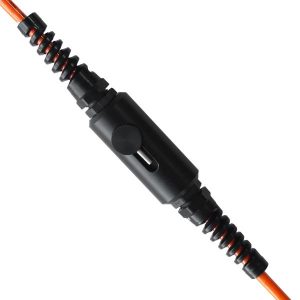
Figure 2: NexSens TS210 Thermistor String
Specifications
|
Sensor Information
|
*On a string with multiple nodes, the nodes will be addressed in increasing numerical order. Use extreme caution when changing the address of a node in a TS210 string to ensure that the nodes remain in numerical order and that the same address is not assigned to more than one node simultaneously.
Third-Party Data Logger Integration
The NexSens UW-Receptacle to Flying Lead cable is an accessory that may be purchased separately for the integration of a TS210 string with a third-party data logger or SCADA system. NexSens X-series data loggers have built-in UW-receptacle ports to accommodate a direct connection of the string. Follow the wiring table below and reference the T-Node FR/TS210 register information to gather readings from the temperature string.
| Receptacle Pin | Wire Color | TS210 Signal |
| 1 | Green | RS485A |
| 2 | Blue | RS485B |
| 3 | Brown | Pass-through |
| 4 | Red | 5-24V+ |
| 5 | White | — |
| 6 | Yellow | Pass-through |
| 7 | Black | GND |
| 8 | Orange | Pass-through |
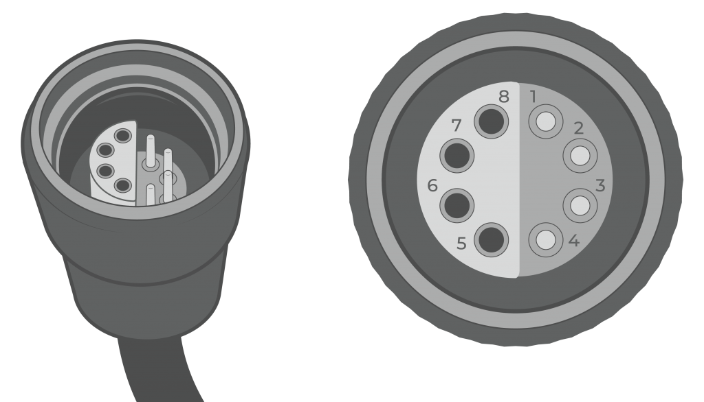
Figure 3: NexSens UW-FLxR pinout.
Integration with NexSens X-Series Loggers
All T-Node FR/TS210 temperature strings must be addressed in increasing numerical order along the string. Modbus RTU allows the sensors to be addressed from 1 to 256. NexSens X-Series data loggers have a pre-defined script that will program the exact number of nodes on the string and gather temperature measurements at a user-specified interval.
1. Change the Modbus Address in the CONNECT software
A single T-Node FR sensor or T-Node FR/TS210 temperature string can be directly connected to a PC using a NexSens RS-485 UW Sensor USB Adapter. This adapter provides the ability to check sensor functionality or adjust the sensor’s Modbus address. Follow the article below to set the addresses for each T-Node FR/TS210 node on the string.
Change the Modbus Address of a TS210 Node
2. Pre-Deployment Check/Setup
It is recommended that field deployments be carefully planned, and it is best to completely configure the system on a lab bench and test it for a period of time prior to taking it to the field. This will ensure a successful deployment and quality data collection. Additionally, it is much easier to troubleshoot problems in the lab than in the field.
TS-Clamp mooring line connection
Temperature strings are frequently attached to a mooring line to keep them fixed in place vertically within a water column. This technique helps to ensure that temperature data is consistently being monitored at the desired depths. With the temperature string laid out on a flat surface, secure each TS210 to the sensor mooring line using TS-Clamp sensor mooring clamps. The TS-Clamp accessory can be used to affix a TS210 thermistor string to a mooring line for deployment.
Cable Armoring
For any TS210 deployment, apply cable armor to all portions of the sensor string that have the potential to wear against irregular surfaces.
3. Automatic Sensor Detection
After setting the node addresses in increasing numerical order and connecting them to the sensor mooring line, the temperature string can be programmed onto the logger via automatic detection.
X-Series Logger Detection and Script Information
The X-Series data loggers include a pre-loaded T-Node FR/TS210 script, which must be enabled before running a sensor detection. Follow the link below to enable the proper script.
| Logger Script Number | Sensor Interface | Baud Rate | Power Type | Warmup Period (sec) | Frame |
| 1000 | RS-485 | 19200 | Switch | 2 | 8N1 |
After the script is enabled, run a sensor detection to program the sensor onto the logger.
Read Sensor Configuration – Confirm Sensor Detection
After ~5-10 minutes, read the sensor configuration to confirm all nodes on the string and other connected sensors have been detected on the data logger. Thoroughly review the parameter list to ensure all parameters are accounted for and are measured in the desired units. Let the unit gather a few readings to confirm accurate and reasonable parameter data.
If a node is not detecting on a NexSens X-Series data logger after following the integration guide, below is a link outlining a few common reasons that should be reviewed.
4. Setting up WQData LIVE
Once an X-Series data logger has finished a new sensor detection, it will automatically push the sensor configuration to the WQData LIVE web data center. Follow the three articles below to create a WQData LIVE account, create a new WQData LIVE project and site, and add the data logger to the project.
- Create a WQData LIVE Account
- Create a Project on WQData LIVE
- Add a Data Logger to a Project on WQData LIVE
Real-Time System Application
Real-time water temperature measurements from the NexSens TS210 temperature string are useful in various environmental monitoring applications.
Applicable Systems
Discover applicable uses for NexSens TS210 temperature strings.
- HABs Detection Systems
- Inland Lake Monitoring Systems
- Large Lake Monitoring Systems
- Temperature Profiling Systems
Case Studies
Read about specific applications using NexSens TS210 temperature strings.
- Managing Plant Discharge Temperatures
- Monitoring Lake Stratification
- Buffalo Pound Lake Algae Blooms
Water Temperature Measurements
Learn more about water temperature measurements on the NexSens Blog Page.