
Change the Modbus Address of a T-Node FR
Each T-Node FR has a factory-assigned Modbus address of 1. When the nodes are assembled in a string, each successive node must have an address 1 greater than the previous node. For example, if the first node in a string of five nodes is addressed 10, the successive nodes must be addressed 11, 12, 13 and 14, respectively. The following process is used to change the address of an individual T-Node FR using the iChart software.
Connection Directly to a PC
A single T-Node FR sensor or T-Node FR/TS210 temperature string can be directly connected to a PC using a NexSens RS-485 UW Sensor USB Adapter. This adapter provides the ability to check sensor functionality or adjust the sensor’s Modbus address.
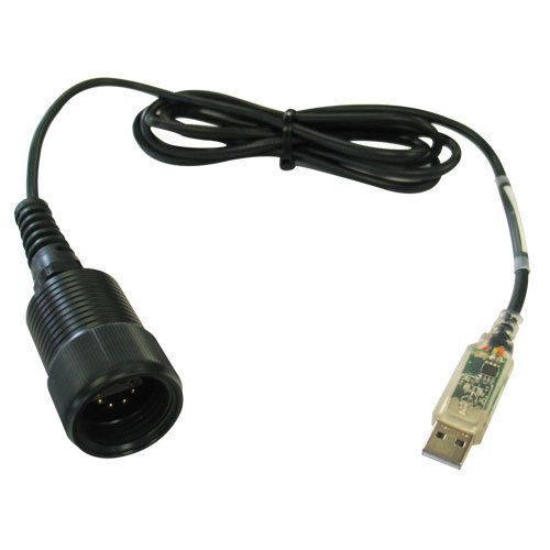
NexSens RS-485 UW Sensor USB Adapter
- Connect the T-Node FR or temperature string directly to the receptacle end of the UW-USB-485R cable.
- Plug the USB adapter into a PC containing the iChart software.
- Open iChart. (It is not necessary to open a current project)
- Open the diagnostic window in iChart by going to View | Diagnostic Window.

Open diagnostic window
- Click Advanced | mv-RS485 Adapter | Setup. The T-Node FR/mV-RS485 Adapter Setup window should appear.
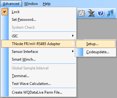
Open Configuration Menu
- Enter the appropriate communication settings and Modbus address of the adapter to be configured. Select the following:
- Connection type: Direct to PC
- Correct COM port. If a COM port is unknown, click here for instructions to identify it.
*If the Modbus address is unknown, the universal address 251 can be used to find the device, but only if it is the only Modbus device connected. Otherwise, the exact address must be entered in the Modbus Address field.
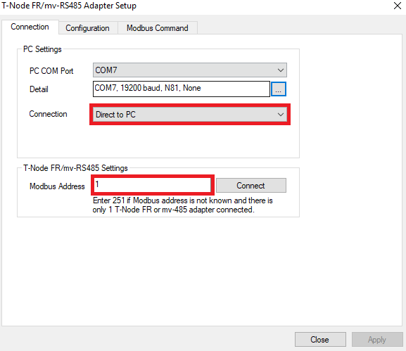
Direct to PC communication settings
- Click the Connect button to open a connection to the device. When the button changes to Disconnect, click the Configuration tab to access the configuration settings. If the current configuration of the device does not show correctly, go back to the Connection tab, check the settings, and retry the connection.
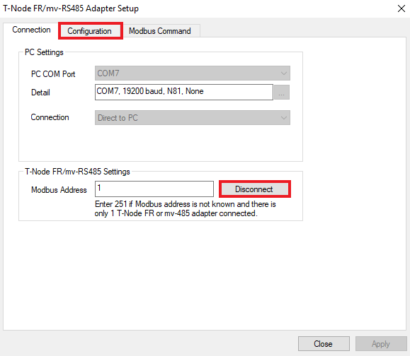
Access configuration menu
- Verify that the T-Node FR configuration has been read successfully. The following output should appear in the diagnostic window with the current T-Node FR sensor address. Additionally, depending on the iChart software version, the firmware, hardware and ID will appear at the bottom of the interface
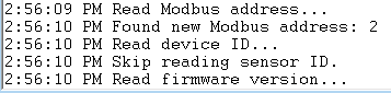
Successfully found modbus address

Configuration Tab
- Check “Edit Modbus Address.”
- Enter the new address. Click Apply.
- Disconnect and reconnect to the T-Node FR using the new Modbus address to confirm the change was applied.
The T-Node FR’s address has been changed. Place the T-Node FR in the appropriate position within the string.
Connection through an iSIC data logger
- Connect the plug end of the T-Node FR with the receptacle port or digital terminal of an iSIC or SDL500 data logger.
- In iChart, go to Advanced | TNode FR/mV-RS485 Adapter.
Open Configuration Menu
- Enter the appropriate communication settings and Modbus address of the adapter to be configured. Select the following:
- Connection type: Through iSIC
- iSIC Address
- Correct COM port. If a COM port is unknown, click here for instructions to identify it.
*If the Modbus address is unknown, the universal address 251 can be used to find the device, but only if it is the only Modbus device connected. Otherwise, the exact address must be entered in the Modbus Address field.
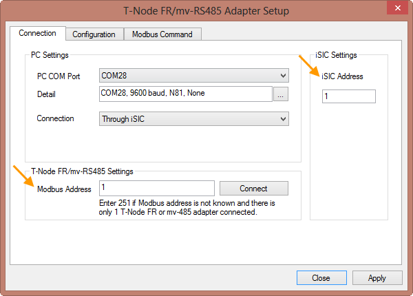
Through iSIC communication settings
- Click the Connect button to open a connection to the device. When the button changes to Disconnect, click the Configuration tab to access the configuration settings. If the current configuration of the device does not show correctly, go back to the Connection tab, check the settings, and retry the connection.

Access Configuration Menu
- Verify that the T-Node FR configuration has been read successfully. The following output should appear in the diagnostic window with the current T-Node FR sensor address. Additionally, depending on the iChart software version, the firmware, hardware and ID will appear at the bottom of the interface
Successfully found modbus address
Configuration Tab
- Check “Edit Modbus Address.”
- Enter the new address. Click Apply.
- Disconnect and reconnect to the T-Node FR using the new Modbus address to confirm the change was applied.
The T-Node FR’s address has been changed. Place the T-Node FR in the appropriate position within the string.