Vaisala WXT-Series Weather Sensor X-Series Integration Guide
Vaisala WXT-Series Weather Sensors provide up to six of the most important weather parameters, including air pressure, temperature, humidity, rainfall, wind speed, and direction. The weather sensors are compatible with NexSens X-Series data loggers using the SDI-12 sensor interface and communication protocol.

Sensor Setup
First, follow the manufacturer’s guidelines to complete sensor setup. Be sure to set the station to Continuous Measurements Mode and adjust the SDI-12 address as needed if connecting other SDI-12 sensors.
Connecting with X-Series Loggers
Next, the Vaisala WXT-Series weather sensor will need to be set up for the X-Series logger using the CONNECT software.
- Connect the sensor using the supplied cable to one of the open sensor ports on the logger and note the port number.
- Enable the pre-loaded sensor profile.
- Configure Sensor Scripts
- Note: The Vaisala weather station is #2002 in the list
- Complete the setup for all other sensors, and then run sensor detection in CONNECT.
- After ~5-10 minutes, read the sensor configuration to confirm detection. Let the unit gather a few readings to confirm that readings are accurate and reasonable.
Mounting
Deployment setups will vary based on the platform, application, and site location. For general buoy mounting instructions and shore-side mounting options, see below.
Buoy-Based Deployments
First, follow the appropriate User Guide in the Knowledge Base for buoy assembly. Then, use the NexSens Vaisala WXT-Series Weather Sensor Buoy Mount to attach the sensor to the buoy cage by following the steps below.
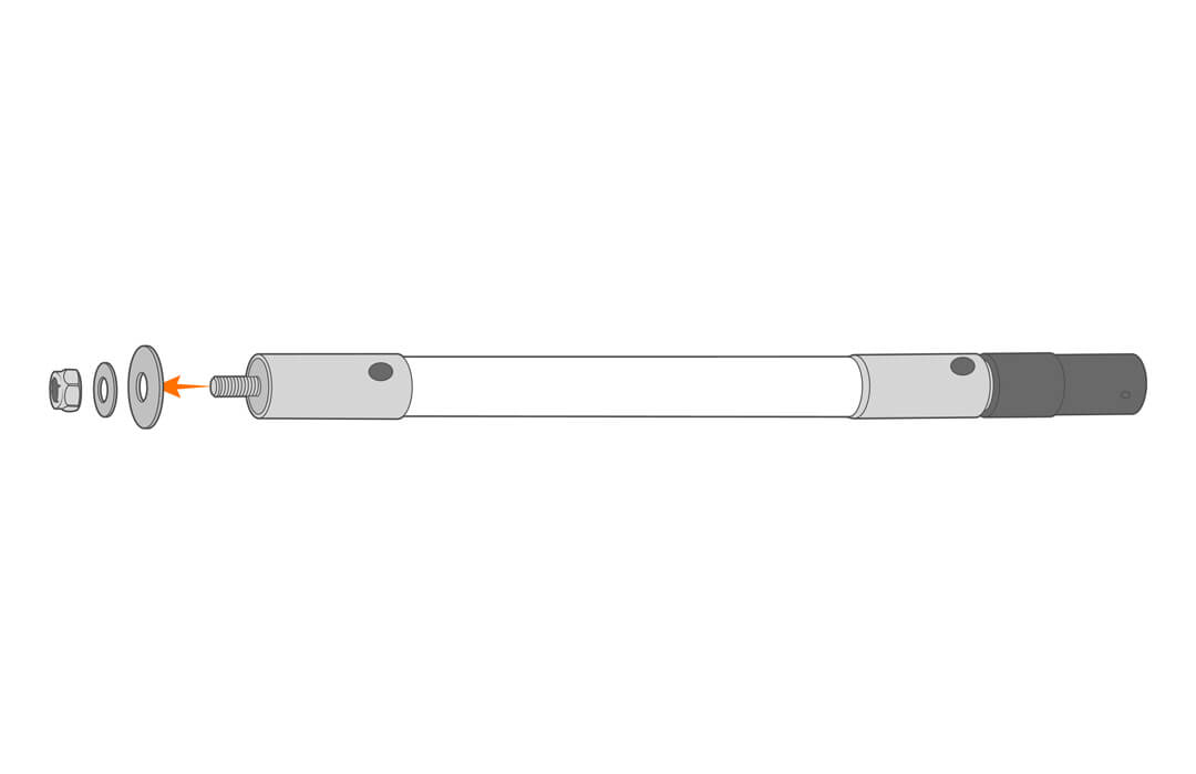
- Remove the included hardware from the threaded end.
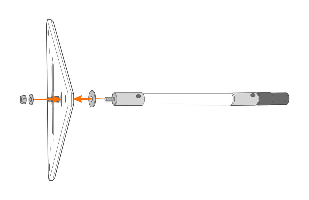
- Secure the mount to the solar tower top plate.
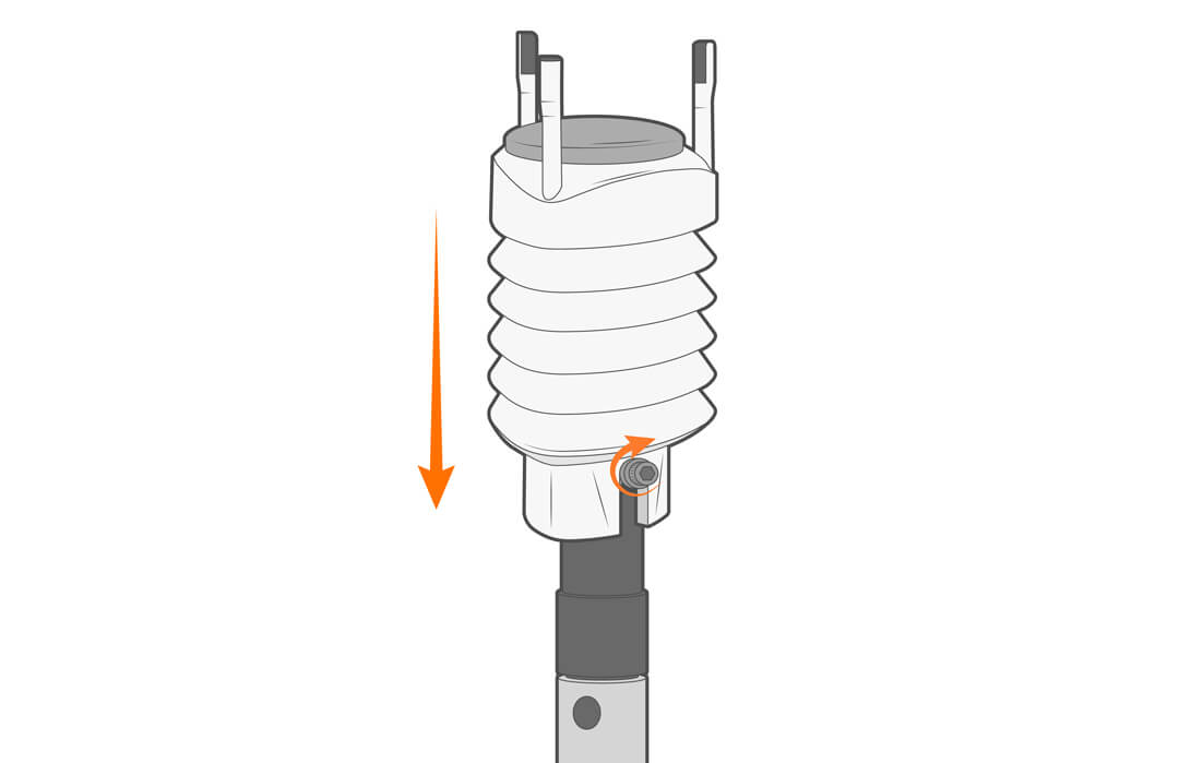
- Place the Vaisala weather station in the hub and tighten in place.