
Communicate Directly with an SDI-12 Sensor
In CONNECT’s X2 Diagnostic feature, users can communicate with and send commands directly to a connected SDI-12 sensor (V2.22.03.03 or later firmware). Direct communication is critical for confirming sensor transmission, determining the sensor’s SDI-12 address, and reviewing the parameter output. Communicate with an SDI-12 sensor through common SDI-12 protocol commands by following the process below.
Note: Set a large log interval for all connected sensors to avoid interfering with a data acquisition while troubleshooting with the SDI-12 terminal.
Access the X2 Diagnostic Feature
- Connect the X2 logger to a PC and launch the CONNECT software. Test connection by reading the RTC clock of the logger in the CONFIG tab.
- Navigate to Tool | X2 Diagnostic.
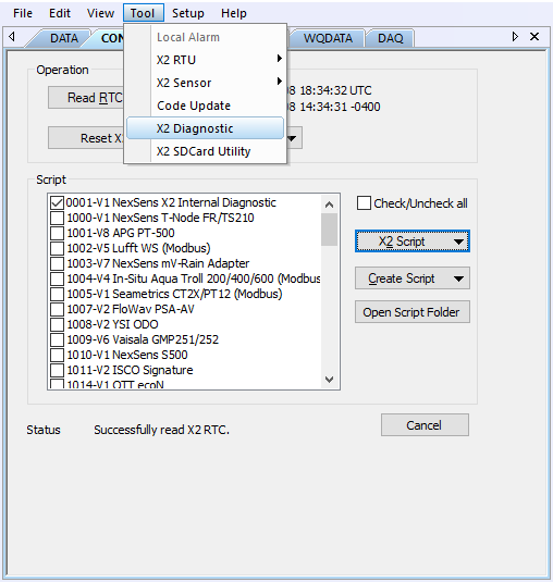
Figure 1: CONNECT X2 Diagnostic feature.
- Once the X2 Diagnostic menu appears, click on the SDI-12 button on the left-hand side to open the SDI-12 communication terminal.
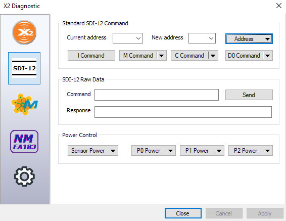
Figure 2: Communicate with SDI-12 Sensor using SDI-12 terminal.
- Begin by turning on the sensor power control (Figure 3) and then providing power to the specific port in which the SDI-12 sensor is connected (Figure 4).
- Note: Power will be supplied to the sensor until the next log interval begins for any of the connected sensors. Once a new data acquisition has taken place, the X2 will remove power from all ports. If sending a common command results in a “Fail!” response thereafter, turn on power to the appropriate port.
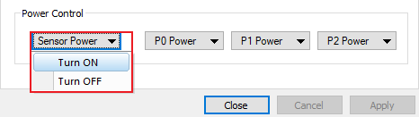
Figure 3: Toggle on sensor power control. |
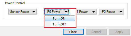
Figure 4: Send power to the specified port. |
Standard SDI-12 Commands
Query Sensor Address
Note: The query address function will only work while a single SDI-12 sensor is connected.
The query address function will send the following SDI-12 command, which will request the sensor’s current SDI-12 address:
- “?!”
A result in this format should then appear:
- “a<CR><LF>”
- Where “a” is a placeholder for the sensor address.
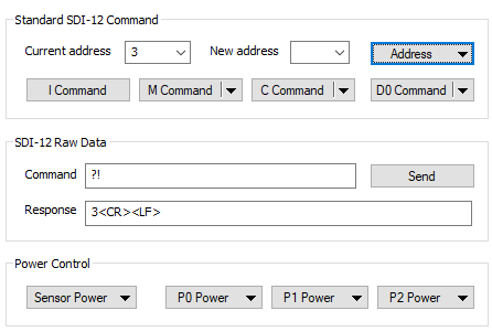
Figure 5: Current SDI-12 address of the sensor.
Change a Sensors Address
Note: Changing the sensor address of a pre-detected sensor will halt regular communication with the data logger. The SDI-12 address of the sensor must match the address of when it was first detected.
If the query sensor address function was sent previously, the current address will appear. Enter a new address in the dialog box, then click Change Address. The change sensor address function will send the following SDI-12 command:
- “aAb!”
- Where “a” is the current sensor address and “b” is the new sensor address.
A result in this format should then appear:
- “b<CR><LF>”
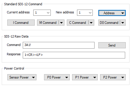
Figure 6: SDI-12 address change from 3 to 1.
Identify (I) the Sensor
The identify (I) function will send the following SDI-12 command, which will request the manufacturer identification for the sensor:
- “aI!”
A result in this format should then appear:
- “allccccccccmmmmmmvvvxxx…xxx<CR><LF>”
- Where:
- “ll” is the SDI-12 version number.
- “cccccccc” is the 8 character manufacturer identification.
- “mmmmmm” is a 6 character sensor model number.
- “vvv” is a 3 character sensor version.
- “xxx…xxx” is an optional field for a sensor serial number or other sensor information.
- Where:
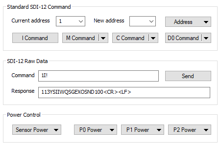
Figure 7: SDI-12 sensor identification.
Send a Measurement (M) Command
The measurement (M) function forces the sensor to measure only a certain set of parameters, depending on the exact command (i.e., M1, M2, M3, etc.) sent. The parameter output for each command will be available in the sensor manual. This function will send the following SDI-12 command:
- “aM!”
A result in this format should then appear:
- “atttn<CR><LF>”
- Where:
- “ttt” is the specified time that the sensor will take to complete the measurement.
- “n” is the number of measurement values the sensor will collect.
- Where:
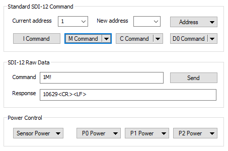
Figure 8: SDI-12 measurement command.
Send a Concurrent Measurement (C) Command
The concurrent measurement (C) function allows multiple SDI-12 sensors to take measurements simultaneously on the same sensor BUS. This function will act similarly to the M command, and the parameters should be outlined in the sensor manual. This function will send the following SDI-12 command:
- “aC!”
A result in this format should then appear:
- “atttn<CR><LF>”
- Where:
- “ttt” is the specified time that the sensor will take to complete the measurement.
- “n” is the number of measurement values the sensor will collect.
- Where:
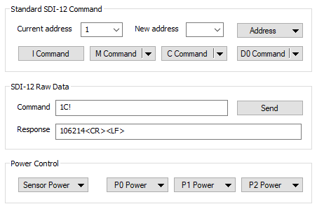
Figure 9: SDI-12 concurrent measurement command.
Send a Data Request (D) Command
The data request (D) command requests the latest measured values from the sensor after sending the M or C command and waiting the specified amount of measurement time. Depending on the number of parameters, different values may be accessed using separate D commands (i.e., D0, D1, D2, etc.). The sensor manual will outline the values associated with each D command. This function will send the following SDI-12 command:
- “aDx!”
- Where “x” is the number for the specific D command selection (i.e., 1, 2, 3, etc.).
A result in this format should appear:
- “a<values><CR><LF>”
- Where:
- <values> are the measurements from the sensor separated by + or – polarity signs indicating a positive or negative value.
- Where:
Note: Depending on the number of parameters output by the sensor, more data points may be available in other D commands.
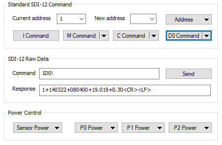
Figure 10: SDI-12 D0 command for data request.
SDI-12 Raw Data
Custom or uncommon SDI-12 messages, not present in the standard SDI-12 command options, may be sent using the SDI-12 raw data terminal. Ensure to review the specific sensor manual before sending commands to understand the proper syntax and expected responses to each command.
For more information on the SDI-12 protocol, visit the following link: