
Turner Submersible Fluorometers X-Series Integration Guide
Real-Time Water Quality Measurements
The Turner Designs C3 and C6P Submersible Fluorometers are designed to incorporate 3 & 6 optical sensors, respectively, ranging from the ultraviolet to the infrared spectrum. The fluorometers are compatible with NexSens X-Series data loggers via the Modbus-RTU communication protocol and the RS-232 sensor interface. A user-generated script can be created to detect, log, and transmit all parameters output by the sensor. Parameter data is transmitted, in real-time, at a user-specified interval (e.g., 10 minutes) to the NexSens WQData LIVE Web Datacenter. There, data is stored on customizable dashboards with statistics and graphical interfaces for each parameter. Users can download and send data reports via Email, FTP, or an API. Below is information on the settings and wiring required to integrate these sensors with a NexSens X-Series data logger.
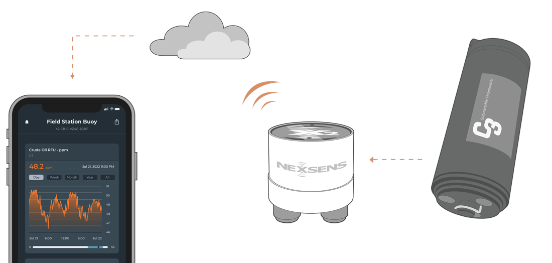
Figure 1: Turner Designs C3 integration with NexSens X-Series data loggers.
Compatible Models
Depending on the optical probes installed, a generic GSI script must be created within the CONNECT software to read the available measurements from the fluorometers. These devices are utilized for a variety of applications to detect materials with fluorescence properties, such as oil, organic matter, cyanobacteria, tryptophan, PTSA dye, rhodamine dye, and turbidity.
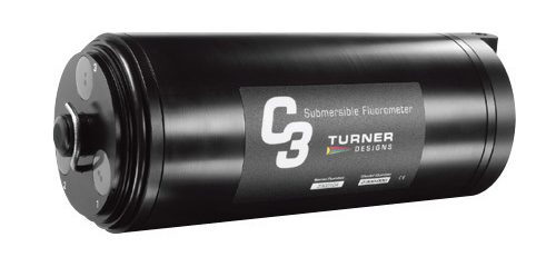
Figure 2: Turner Designs C3 Submersible Fluorometer. |
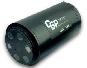
Figure 3: Turner Designs C6 Submersible Fluorometer. |
Turner Designs Fluorometer Integration
For communication with an external data logger, the C3 & C6P submersible fluorometers must have the integrator firmware installed. This firmware produces a continuous serial output stream (1Hz) from the sensor after a 15-second warmup interval. Additionally, the wiper will wipe once upon powerup and every 5-minutes as long as power is continuously applied. Applying this firmware allows the X2 data logger to properly gather accurate measurements from the unit after a generic GSI script is created.
1. Install the Integrator Firmware, C-Soft software, and TI Downloader
The integrator firmware can be uploaded to the Turner C3 using the TI Downloader software. The integrator firmware, C-Soft software, and TI Downloader can be downloaded at the following link:
Once these items are downloaded, follow the Firmware Update Instructions at the link below to complete the firmware update.
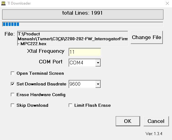
Figure 4: TI Downloader loading on integrator firmware.
2. Adjust Settings in the C-Soft Software
Use the same cable utilized for the firmware update to communicate with the fluorometer in the C-Soft software. Follow the instructions to properly set up the sensor for communication with the X2 data logger.
- Once the C-Soft software is opened, choose the correct COM port. The software will begin initializing the unit once connection is established.
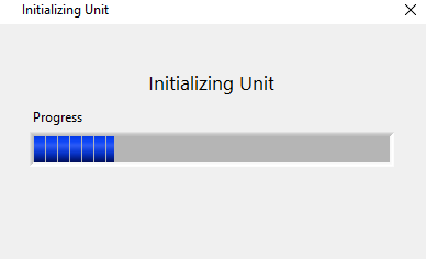
Figure 5: C-Soft software initializing the fluorometer unit.
- Under Settings ensure the proper channels are enabled and the appropriate sensors are available.
- Note: The depth sensor is an optional accessory; however, the depth parameter will still output from the sensor. Depth must be an included parameter and in the proper location for the script created below.
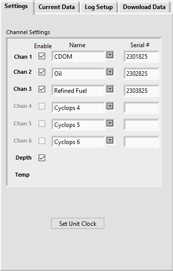
Figure 6: Turner C3 example settings.
- Open the Current Data tab and note the parameter list.
- This list, along with the exact order, will be vital in creating the generic GSI script in the CONNECT software.
- It is beneficial to note the approximate values output from each parameter to cross-reference these values in the future.
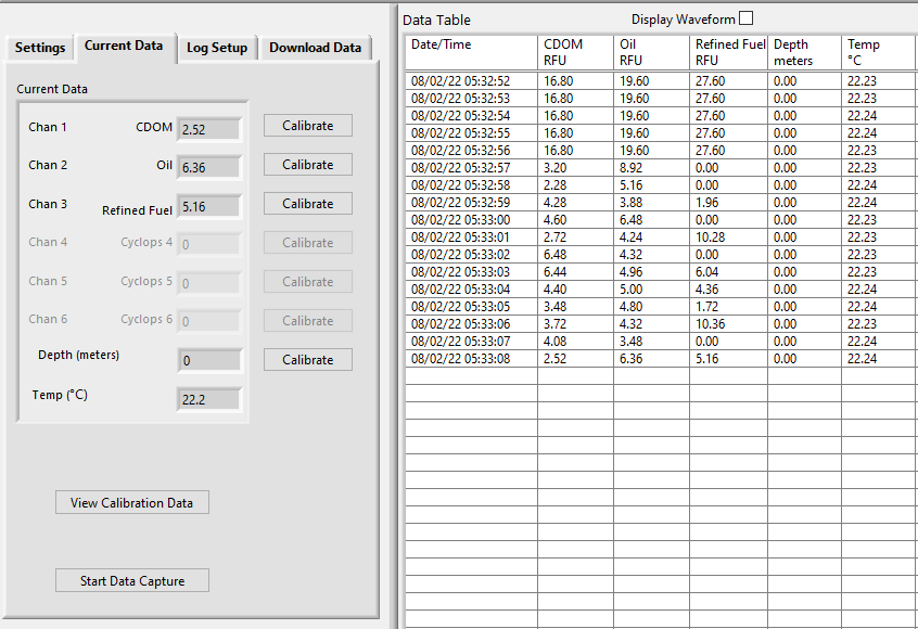
Figure 7: Turner C3 example data output.
- Go to the Log Setup tab, enable the wiper, and enable the Datalog.
- With the integrator firmware installed, the wiper will wipe once upon powerup and every 5 minutes with power applied continuously.
- The Datalog option must be the last item selected. This features enables datalogging output for the external X2 data logger.
- Select “Yes” to the warning message that displays.

Figure 8: Enable wiper and datalog in log setup.
3. Automatic Sensor Detection
The Turner C3 and C6P submersible fluorometers are manufactured according to users’ optical specifications, thus, the parameters measured by each fluorometer are dependent on the installed probes. Each fluorometer comes with a factory-installed temperature probe and an optional depth sensor. It is imperative that the user confirm the output from the fluorometer in the C-soft software (above) before creating a generic GSI script in CONNECT.
X2 Script Information & Sensor Parameters
Create a generic GSI script through the CONNECT Software with the following settings:
- Manufacturer: Turner Designs
- Model: C3 or C6 (Dependent on the model of the fluorometer)
- Port: P0, P1, or P2
- Ensure to connect the sensor to the port number selected in the script.
- Baud: 9600 is the default for the C3 and C6 fluorometers.
- Power: Switch
- Continuous power is not recommended as these fluorometers require a substantial power draw.
- Timeout: 3 seconds is the default.
- Connection: RS-232
- Frame: N81
- Warmup: >30 seconds
- With the integrator firmware installed, the fluorometer has an automatic 15-second warmup. NexSens recommends leaving the warmup at 30 seconds or greater to allow measurement stability.
- Avg Duration: The CONNECT script will average measurements over a certain duration of time. Since the fluorometers output at 1Hz, a 10-second average duration would provide an average of 10 overall measurements.
- Available Parameters – Construct the appropriate parameter output list for the sensor by assigning parameters to the Selected Parameters column using the Add/Remove/Move Up/Move Down buttons.
- The total number and ordering of parameters for the script must match the parameter output for the sensor.
- If the sensor outputs a diagnostic or undesirable parameter (e.g., date and time) as a part of its measurement command, it can be omitted from logging to the X2. Substitute the _None parameter into its position on the Selected Parameters list.
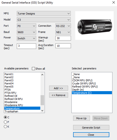
Figure 9: Example script generation for Turner C3 fluorometer.
Script Generation
- Once the script settings have been outlined, click Generate Script in the bottom right corner of the menu, assign a script number, and click OK.
- If multiple generic scripts will be created for the X2, assign a unique value to each.
- If modifications need to be made to an existing generic script, assign the same script number to overwrite the original.
- The generic script will be saved in the CONNECT software folder.
Figure 10: Successfully generated script.
- Follow the Configure Sensor Scripts document to:
- Transfer the new script to the X2 (demonstrated in the Add/Update Sensor Scripts section).
- Read the existing X2 script list (shown in the Show Enabled Sensors section).
- Enable the custom script to run during sensor detection (demonstrated in the Modify Sensor Detection List section).
- Connect all sensors, apply 12V power, and run sensor detection in CONNECT (alternatively, by queuing the Sensor (Auto)Detection command from WQData LIVE or through the X2 embedded web).
- Once the detection command is received, the generic script will be run. As long as the sensor responds to the X2 according to the script settings, it will be identified, and data collection and posting to WQData LIVE will begin.
4. Setting up WQData LIVE
Once an X-Series data logger has finished a new sensor detection, it will automatically push the sensor configuration to the WQData LIVE Web Datacenter. Follow the three articles below to create a WQData LIVE account and a project/site. Then add the data logger to the project using the included claim code.
- Create a WQData LIVE Account
- Create a Project on WQData LIVE
- Add a Data Logger to a Project on WQData LIVE
Real-Time System Application
Real-time water quality measurements from the Turner Designs C3 and C6P Submersible Fluorometers are useful in various environmental monitoring applications.
Applicable Systems
Fluorescence measurements from the Turner C3/C6P Submersible Fluorometers are useful in various environmental monitoring applications.
Case Studies
Read about specific applications using Turner Designs C3 and C6P Submersible Fluorometers.
- Expanding Algal Bloom Monitoring Network
- Lake Lacawac Profiling Platform
- Washington Dam Hydrology Tracking
- Monitoring Platform Protects Native Culture
- Michigan’s Muskegon Lake Sentinel
- Experimental Sensors For Lake Erie
- Drinking Water Early Warning System
Water Quality Measurements
Learn more about water quality measurements on the NexSens Blog Page.
- Water Quality Sensor Options
- Source Water Monitoring – Raw Water Intake
- Turbidity Monitoring at Dredge Sites
Sensor Manual
For additional information on the Turner Designs C3 and C6P Submersible Fluorometers, please refer to the Turner Designs User Manual.