SeaView Systems SVS-603HR Wave Sensor X-Series Integration Guide
Real-Time Wave Measurements
The SeaView Systems SVS-603HR Wave Sensor is a highly accurate wave sensor that reports heading, wave height, wave period, and wave direction. The sensor is compatible with NexSens X-Series data loggers via the Modbus-RTU communication protocol and the RS-232 sensor interface. A pre-defined script on X-Series data loggers is able to detect, log, and transmit all parameters programmed to output from the sensor. Parameter data is transmitted, in real-time, at a user-specified interval (e.g., 10 minutes) to the NexSens WQData LIVE Web Datacenter. There, data is stored on customizable dashboards with statistics and graphical interfaces for each parameter. Users can download and send data reports via Email, FTP, or an API. Below is information on the settings and wiring required to integrate these sensors with a NexSens X-Series data logger.
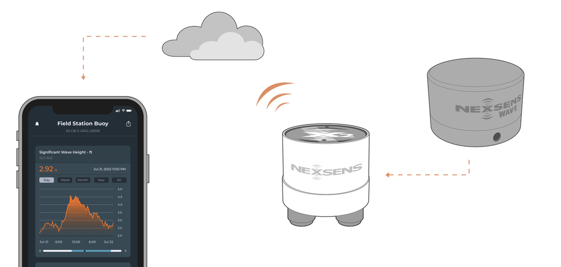
Figure 1: SeaView Systems SVS-603HR Wave Sensor integration with NexSens X-Series data loggers.
Compatible Models
SeaView Systems offers multiple models (SVS603, SVS603HR, & SVS603 HRi) of the SVS-603 wave sensor with varying capabilities that are compatible with NexSens X-Series data loggers. Using a pre-defined hex code, the user can control the parameter output from the sensor with the most pertinent information. The internal script on the data logger will read this code upon detection to determine and log the parameter list.
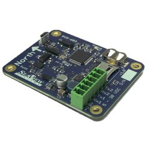
Figure 2: SeaView Systems SVS603, SVS603HR, and SVS603HRi wave sensor.
Wave Sensor Integration
NexSens provides two models of wave sensor housing for mounting on a NexSens CB-Series buoy. Instructions for mounting can be found here. NexSens engineers will install and program the sensor according to user specifications before shipment. In the event that a user purchase a wave sensor separately, below is the wiring information and settings required for integrating with a NexSens X-Series data logger.
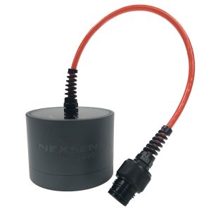 Figure 3: Wave sensor enclosure for SVS-603 base model. | 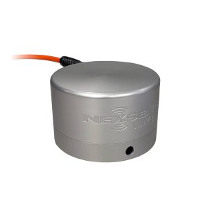 Figure 4: Wave sensor enclosure for SVS-603HR model. |
1. Wiring
The SVS-603HR in a NexSens wave sensor housing includes a connectorized UW8 plug to flying lead wires. These wires route internally into the wave sensor housing for connection of power, ground, and RS-232 Tx/Rx with the wave sensor terminal strip. For CBMC data logger models with an MCIL-8 plug, contact NexSens for information on the overall wiring.
| NexSens UW8 Plug Pin | Signal | SVS-603HR Board Identifier | NexSens UW8 Wire Color |
| 1 | RS-232 Tx | Rx1 | Orange |
| 2 | GND | 0V | Black |
| 3 | RS-232 Rx | Tx1 | Yellow |
| 5 | 12VDC+ | +V | Red |
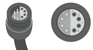
Figure 5: UW8 Plug pin numbers
2. Establish Communication and change internal settings
The Seaview SVS-603HR wave sensor can be configured using a terminal emulator program and a micro-USB cable. NexSens utilizes the Tera Term software for communication with the wave sensor.
- Set the terminal emulator serial port communication to the following:
- Baud rate: 9600
- Data: 8 bit
- Parity: None
- Stop: 1 bit
- Flow Control: None
- Connect the micro-USB to the port shown in the image below and plug the USB end into a PC.
- The Status LED should flash red and begin blinking each second.
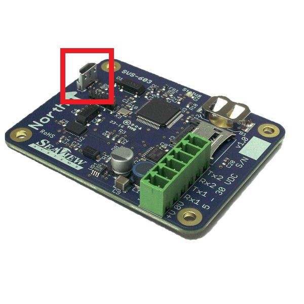
Figure 6: SVS-603HR sensor with micro-USB port outlined.
Adjust the Output Settings
- Commands must be sent to the wave sensor for proper communication with the X2 data logger. All commands utilize a “set” and “get” option to apply new settings or read current settings, respectively. Commands following the “set” option will be followed by a specified number below. Use the “get” option followed by the command to read the current settings. The following commands must be set on the SVS-603HR:
- set outputser 00152427
- Sets a hex code for the wave sensor to output the parameters within the X2 script.
- More parameters are available using a different hex code; however, these are the most commonly utilized and are the ones set up during integration at NexSens by default.
- set polling 1
- This setting allows the X2 data logger to perform a polling operation that will gather the current output from the sensor.
- set summaryser 0
- The summary output will be disabled so the X2 data logger can gather measurements at any point during the sensor sampling period.
- set outputser 00152427
- Once all commands have been sent and verified with the “get” option, enter reset in the terminal. Then enter the get all command to verify the wave sensor settings. Below are the required settings for integration with an X2-series data logger.
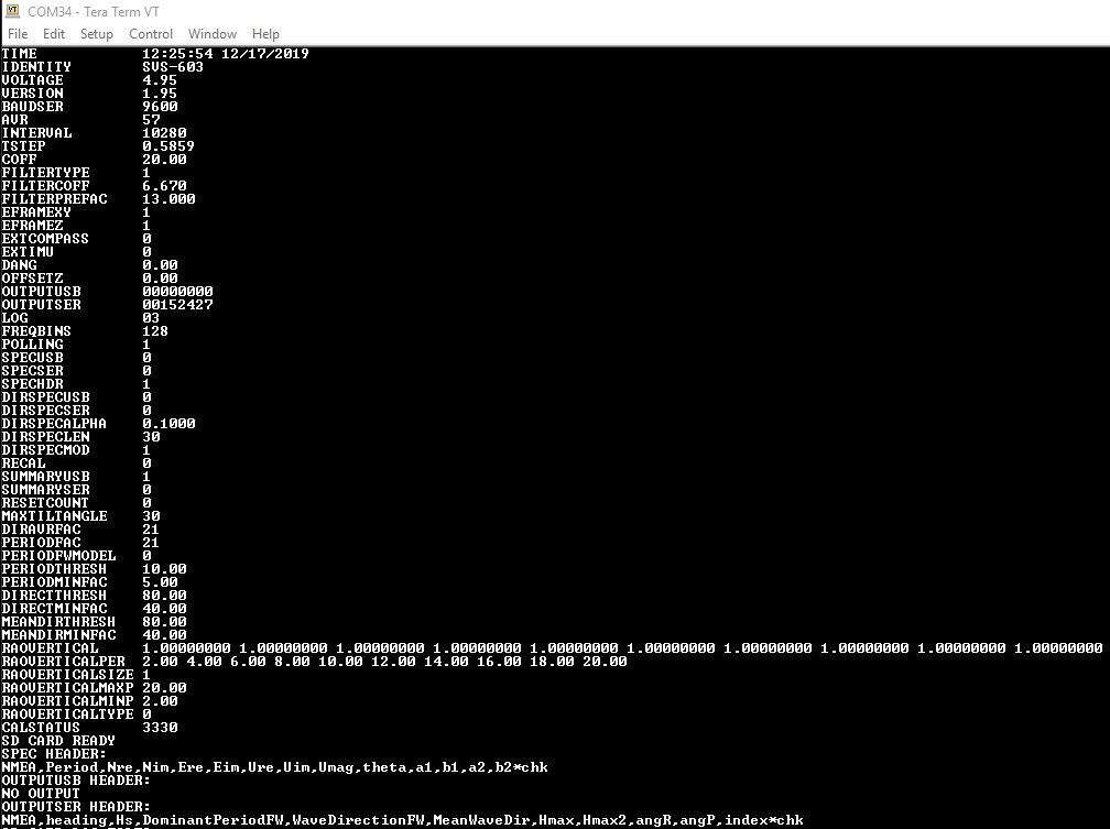
Figure 7: Required settings for communication with a NexSens X2-series data logger.
Sample Rate Note
By default, the SVS-603HR will sample at a ~1.72 Hz rate to complete 2048 samples in 19.794 minutes. After 2048 samples are collected, the wave sensor will output summary values that are then polled and recorded by the X2 as the final measurement and will begin a new 2048 sample set. Thus, it is recommended to set the log and sample interval for the wave sensor to 20 minutes or greater on the X2. Otherwise, data will be repeated as the summary data will remain on the wave sensor until another 2048 sample set is complete. As a rule, the log and sample interval must always be greater than the SVS-603HR sample rate.
3. Automatic Sensor Detection
After adjusting the internal communication settings, the sensors and their parameters can be programmed onto the logger via automatic detection.
X-Series Script Information
The X2 data logger includes a pre-loaded SVS-603HR script. Use the CONNECT software to enable the script for sensor detection.
| X2 Script Number | Sensor Interface | Baud Rate | Power Type | Warmup Period (sec) | Timeout (ms) | Frame |
| 3014 | RS-232 | 9600 | Continuous | 10 | 1130 | N81 |
Default Script Parameters
The following parameters are based on the outputser hex code outlined in the “Configure Communication” section. More parameters are available with the SVS-603HR wave sensor using a different hex code; however, these are the most commonly utilized parameters and are the ones set during integration at NexSens facility.
| Parameter | Unit | Description* |
| Heading | Degrees | Compass heading degrees (North arrow on sensor is true north; 0 degrees) |
| Hs Wave Height (Significant wave height) | Meters | Average of the highest one-third of all wave heights during the 20-minute sampling period. |
| TP (DPD) Wave Period | Seconds | Period calculated with the maximum wave energy. |
| Dominant Wave Direction | Degrees | Dominant wave direction during the sampling period. (Degrees from N). |
| Mean Wave Direction | Degrees | The direction from which the waves at the dominant period (DPD) are coming. |
| Hmax Wave Height | Meters | Maximum wave height within the sampling period. |
| H10 Wave Height | Meters | Average of the highest 10% of waves within the sampling period. |
| Pitch | Degrees | Rotation around the side-to-side axis. |
| Roll | Degrees | Rotation around the front-to-back axis. |
| Sample Number | — | Current sample number between 0-2047. Sample number will start from 0 again on the 2048th sample. |
*The SVS-603HR parameters follow the NOAA Standard for Meteorological Data. More information can be found at the NOAA National Data Buoy Center.
Read Sensor Configuration – Confirm Sensor Detection
After ~5-10 minutes, read the sensor configuration to confirm the sensors have been detected on the data logger. Thoroughly review the parameter list to ensure all parameters are accounted for and are measured in the desired units. Let the unit gather a few readings to confirm accurate and reasonable parameter data.
4. Setting up WQData LIVE
Once an X-Series data logger has finished a new sensor detection, it will automatically push the sensor configuration to the WQData LIVE Web Datacenter. Follow the three articles below to create a WQData LIVE account and a project/site. Then add the data logger to the project using the included claim code.
- Create a WQData LIVE Account
- Create a Project on WQData LIVE
- Add a Data Logger to a Project on WQData LIVE
Real-Time System Application
Real-time wave measurements from the SeaView Systems SVS-603HR Wave Sensor are useful in various environmental monitoring applications.
Applicable Systems
Discover applicable uses for the SeaView Systems SVS-603HR Wave Sensor.
Case Studies
Read about specific applications using the SeaView Systems SVS-603HR Wave Sensors.
- Sturdy Little Buoy, Tremendous Predictive Power
- A New Kind of Sentinel on Lake Superior
- Lighter Buoys Mean Quicker, In-House Responses
Wave Measurements
Learn more about buoy-based wave measurements on the NexSens Blog Page.