
YSI H-3401 Tipping Bucket Rain Gauge X-Series Integration Guide
Real-Time Precipitation Measurements
The YSI H-3401 Tipping Bucket Rain Gauges are compatible with NexSens X-Series data loggers using the SDI-12 sensor interface and communication protocol. A pre-defined script on NexSens X-Series data loggers is able to detect, log, and transmit all precipitation parameters on the rain gauge. Parameter data is transmitted, in real-time, at a user-specified interval (e.g., 10 minutes) to the NexSens WQData LIVE Web Datacenter. There, data is stored on customizable dashboards with statistics and graphical interfaces for each parameter. Users can download and send data reports via Email, FTP, or an API. Below is information on the settings and wiring required to integrate these sensors with a NexSens X-Series data logger.
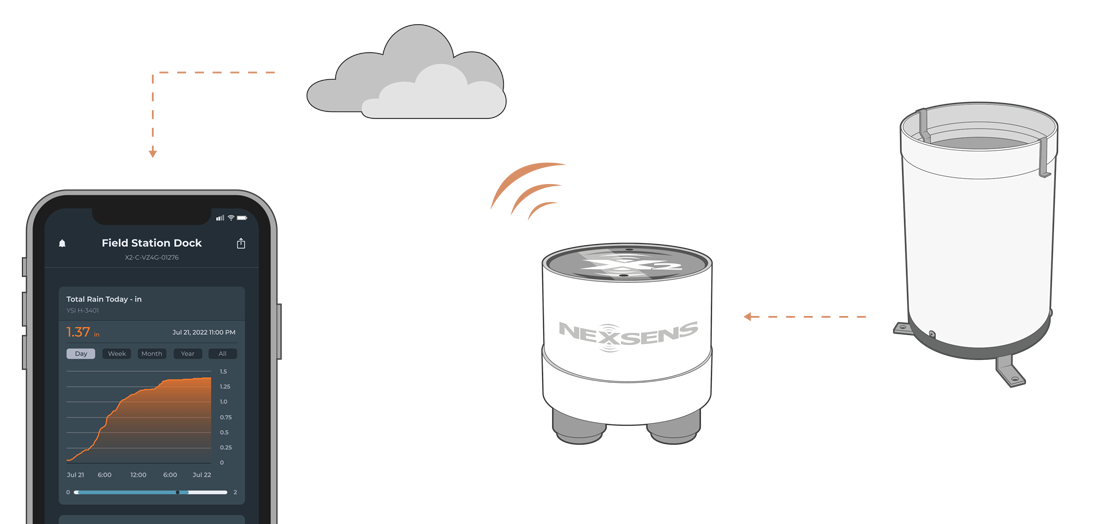
Figure 1: YSI H-3401 Tipping Bucket Rain Gauge integration with NexSens X-Series data loggers for real-time precipitation measurements.
Compatible Models
The rain gauge must have SDI-12 output to communicate with the X-Series data logger. YSI produces three rain gauges with SDI-12 output that differ in their tip measurement (i.e., 0.01″, 0.1mm, or 0.2mm per tip). The tip amount will not affect the integration of the gauge with the data logger.
- H-3401-00-01: 0.01″ per tip
- H-3401-01-00: 0.1mm per tip
- H-3401-02-01: 0.2mm per tip
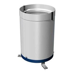
Figure 2: YSI H-3401 Tipping Bucket Rain Gauges.
Sensor Integration
Using SDI-12 communication, the rain gauge will output a standard parameter list after receiving an SDI-12 command from the logger. The internal script sends this command before each reading. The rain gauge will need to be wired for power, ground, and SDI-12 communication for proper readings from the sensor.
1. Wiring
In nearly all applications, a custom connectorized NexSens UW8 plug to flying lead cable will be wired directly into the rain gauge. Below is the necessary wiring information.
| NexSens flying lead cable wire color** | Internal rain gauge cable wire color | Signal |
| Orange/Orange stripe | Red | +12VDC |
| Brown/Brown stripe | Yellow | SDI-12 Data |
| Blue/Blue stripe | Black | Ground |
| N/C | Green | Shield |
| N/C | Brown | Bucket switch A* |
| N/C | Orange | Bucket switch B* |
*Do not remove or switch the bucket switch connections.
**Confirm the cable model with NexSens before wiring to the sensor. The cable outlined in the table is custom and not the standard NexSens UW8 to flying lead cable.
2. Configure Internal Settings
The YSI rain gauge must have a unique SDI-12 address in comparison to other connected SDI-12 sensors. Additionally, the real-time clock on the gauge must be set before deployment to track the time and reset “today’s” and “yesterday’s” accumulation values.
Setting a Unique SDI-12 Address
If the rain gauge is the only SDI-12 sensor connected to the data logger, the default SDI-12 address of 0 shall remain. If another SDI-12 sensor is connected, use the CONNECT software to confirm communication and change the rain gauge (or another sensor) to a unique SDI-12 address.
Setting the Current Time
The built-in real-time clock battery is able to track the current time even when sensor power is removed. However, drifts in the overall time may occur after an extended period. Before deployment, it is recommended to read the current clock time and adjust it if it differs from the actual time. Below are the commands for reading the current time and updating the time on the sensor.
| Command | Example Response | Description |
| aXGT! | a0013<cr><lf> | Read the current time of day |
| Subsequent Command | Example Response | |
| aD0 | a+HH+MM+SS<cr><lf> | |
| Where | ||
| a = Sensor address XGT = Upper case SDI-12 command characters D0 = Data request command HH = Hours (24-hour format) MM = Minutes SS = Seconds |
||
| Command | Example Response | Description |
| aXSTHHMMSS! | a0013<cr><lf> | Set the current time of day |
| Subsequent Command | Example Response | |
| aD0 | a+HH+MM+SS<cr><lf> | |
| Where | ||
| a = Sensor address XST = Upper case SDI-12 command characters D0 = Data request command HH = Hours (24-hour format) MM = Minutes SS = Seconds |
||
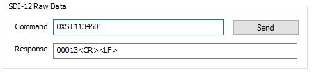
Figure 3: Current time set to 11:34:50. |
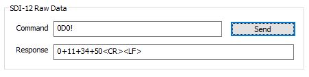
Figure 4: Displaying the new current time. |
Setting the Daily Reset Time
A “reset time” can be programmed onto the sensor to automatically update its “yesterday’s total accumulation” and “today’s total accumulation” values. Once the reset time is reached at each day, the “today’s total accumulation” resets to zero and “yesterday’s total accumulation” is logged internally.
| Command | Example Response | Description |
| aXGDRT! | a0013<cr><lf> | Read the daily reset time |
| Subsequent Command | Example Response | |
| aD0 | a+HH+MM+SS<cr><lf> | |
| Where | ||
| a = Sensor address XGDRT = Upper case SDI-12 command characters D0 = Data request command HH = Hours (24-hour format) MM = Minutes SS = Seconds |
||
| Command | Example Response | Description |
| aXSDRTHHMMSS! | a0013<cr><lf> | Set the daily reset time |
| Subsequent Command | Example Response | |
| aD0 | a+HH+MM+SS<cr><lf> | |
| Where | ||
| a = Sensor address XSDRT = Upper case SDI-12 command characters D0 = Data request command HH = Hours (24-hour format) MM = Minutes SS = Seconds |
||
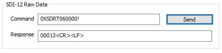
Figure 5: Current daily reset time set to 6:00:00. |

Figure 6: Displaying the new daily reset time. |
3. Automatic Sensor Detection
After setting a unique SDI-12 address, a script can be generated to read the available parameters from the sensor.
X-Series Logger Detection and Script Information
During NexSens integration, a 4000-level script will be added to the X-Series data logger before shipment. If the sensor is purchased separately, contact NexSens to procure the script or create the script using the Generic SDI-12 Script Utility with the following parameters.
| CONNECT Parameter Name | Default Units | YSI H-3401 Parameter Description |
| Interval Rain | mm or in (Dependent on gauge model) |
Rainfall accumulation since the last measurement. |
| Parm 01 | counts | Number of raw bucket tips since the last measurement. |
| Total Rain | mm or in (Dependent on gauge model) |
Total rainfall accumulation since the last reset. |
| Parm 02 | mm or in (Dependent on gauge model) |
Total rainfall accumulation today. |
| Parm 03 | mm or in (Dependent on gauge model) |
Total rainfall accumulation yesterday. |
Run the Sensor Detection
Once the script is created, transfer and enable it on the data logger.
After the script is enabled, run a sensor detection to program the sensor onto the logger.
Read Sensor Configuration – Confirm Sensor Detection
After ~5-10 minutes, read the sensor configuration to confirm the YSI rain gauge and other sensors have been detected on the data logger. Thoroughly review the parameter list to ensure all parameters are accounted for and are measured in the desired units. Let the unit gather a few readings to confirm accurate and reasonable parameter data.
4. Setting up WQData LIVE
Once an X-Series data logger has finished a new sensor detection, it will automatically push the sensor configuration to the WQData LIVE Web Datacenter. Follow the three articles below to create a WQData LIVE account and a project/site. Then add the data logger to the project using the included claim code.
- Create a WQData LIVE Account
- Create a Project on WQData LIVE
- Add a Data Logger to a Project on WQData LIVE
Real-Time System Application
Real-time precipitation measurements from YSI H-3401 Tipping Bucket Rain Gauges are useful in various environmental monitoring applications.
Applicable Systems
Discover applicable uses for YSI H-3401 Tipping Bucket Rain Gauges.
- Flood Warning Systems
- Green Roof Monitoring Systems
- Rain Alert Systems
- Stormwater Monitoring Systems
Case Studies
Read about specific applications using YSI H-3401 Tipping Bucket Rain Gauges.
Precipitation Measurements
Learn more about the importance of precipitation measurements on the NexSens Blog Page.
Sensor Manual
For additional information on YSI H-3401 Tipping Bucket Rain Gauges, please refer to the YSI H-3401 User Manual.