
In-Situ AquaTroll X-Series Integration Guide (SDI-12)
Real-Time Water Quality Measurements
The In-Situ Series of Multi-Parameter Water Quality Sondes (AquaTroll 200/400/500/600) are compatible with NexSens X-Series data loggers via the SDI-12 communication protocol and sensor interface. A user-generated script on NexSens X-Series data loggers can detect, log, and transmit all parameters output by the In-Situ sondes. Parameter data is transmitted, in real-time, at a user-specified interval (e.g., 10 minutes) to the NexSens WQData LIVE Web Datacenter. There, data is stored on customizable dashboards with statistics and graphical interfaces for each parameter. Users can download and send data reports via Email, FTP, or an API. Below is information on the settings and wiring required to integrate these sensors with a NexSens X-Series data logger.

Figure 1: In-Situ AquaTroll Multi-Parameter Water Quality Sonde integration with NexSens X-Series data loggers.
Compatible Models
In-Situ offers four sonde models that are compatible with NexSens X-Series data loggers – the AquaTroll 200, 400, 500 and 600. By adjusting only a few settings using the In-Situ Modbus Sensor Communication Device Kit or the NexSens UW-USB-485R-DC, the sensor can be ready for integration.
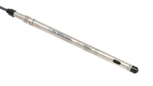
Figure 2: In-Situ AquaTroll 200 Multi-Parameter Water Quality Sonde
|
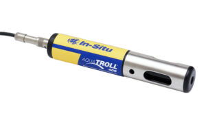
Figure 3: In-Situ AquaTroll 400 Multi-Parameter Water Quality Sonde
|
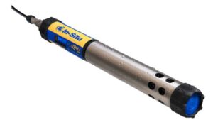
Figure 4: In-Situ AquaTroll 500 Multi-Parameter Water Quality Sonde |
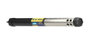
Figure 5: In-Situ AquaTroll 600 Multi-Parameter Water Quality Sonde |
In-Situ Sonde Integration
All In-Situ Sondes integrated at NexSens will require either a receptacle to flying lead cable to interface with the sensor using the In-Situ Modbus Sensor Communication Device Kit or the NexSens UW-USB-485R-DC. The communication cables allow the user to adjust internal settings and calibrate the sensor as necessary.
1. Wiring for Software Communication
AquaTroll Water Quality Sondes can be configured using the Win-Situ 5 software and communication device kit provided by In-Situ. If the sensor has a NexSens UW8 plug connection, a UW-FLxR can connect to the In-Situ communication kit following the wiring table below.
| Communication Kit Color Indicator | Signal | NexSens UW-FLxR Wire Color |
| Blue | RS-485 A (+) | Green |
| Green | RS-485 B (-) | Blue |
| Black | Ground | Black |
| Red | Power | Red |
2. Configure Communication Settings
- Connect the USB cable to a PC that contains the latest version of the Win-Situ 5 software.
- Open the Win-Situ 5 software.
- Go to Preferences | Comm Settings to insert the correct COM port and address for the sensor for the initial connection.
- Brand new sensors should have address 1 and Even parity.
- Click the checkmark at the bottom once the proper changes are made.
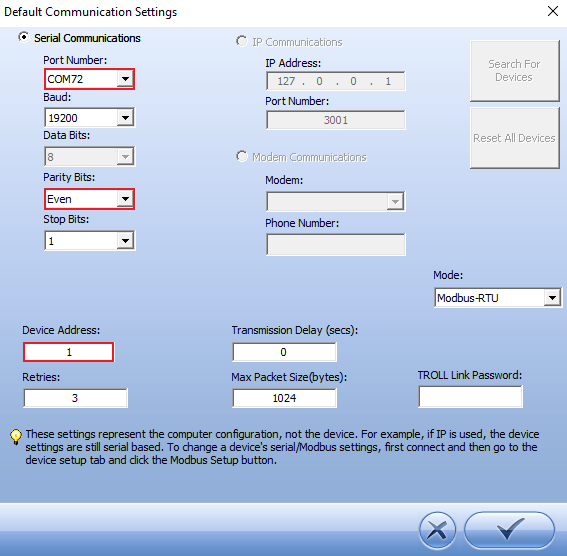
Figure 6: Default communication settings for initial connection.
- Go to File | Connect to connect to the device.
- Travel to the tools icon once connected to the device and click on the SDI-12 Setup.
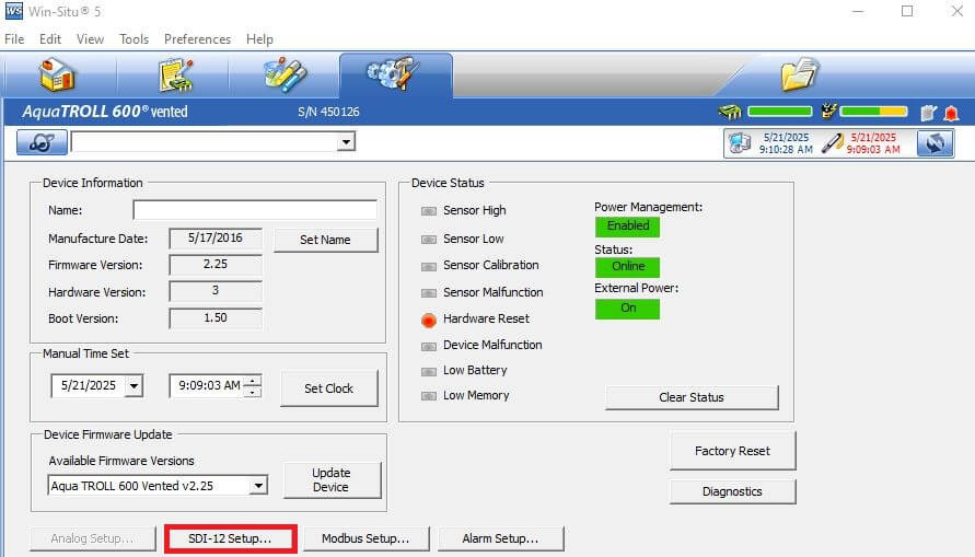
Figure 7: SDI-12 settings setup.
- Select each sensor connected to the sonde and add the appropriate parameters to the output list. Change the SDI-12 address if it interferes with other sensors.
- Ensure to note the SDI-12 address, the order of the parameters, and the units for each parameter for script generation later.
- Click the check mark when finished.
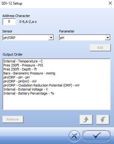
Figure 8: SDI-12 Parameter Output.
3. Automatic Sensor Detection
The user must create a Generic SDI-12 script through the NexSens CONNECT software to communicate and gather measurements from the sonde. For proper configuration, the user must reference the sensor’s SDI-12 address (default=0) and parameter output.
SDI-12 Script Generation
The SDI-12 script utility includes the In-Situ manufacturer and a list of AquaTroll models. The measurement command should always be ‘C’, which allows for measurements to be obtained concurrently with other SDI-12 sensors connected to the logger. Switch power provides a balance between power consumption and data accuracy.
| Manufacturer | Model | SDI-12 Address | Port* | Warmup | Measurement Command | Power |
| In-Situ | Select AquaTroll model | 0-9 (Default = 0) | P1 or P2 | 30 seconds (Recommended) | C | Switch |
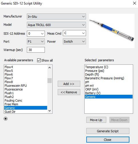
Figure 9: Example script generation for AquaTroll 600.
Run the Sensor Detection
Once the script is created, transfer and enable it on the data logger.
After the script is enabled, run a sensor detection to program the sensor onto the logger.
Read Sensor Configuration – Confirm Sensor Detection
After ~5-10 minutes, read the sensor configuration to confirm the sensors have been detected on the data logger. Thoroughly review the parameter list to ensure all parameters are accounted for and are measured in the desired units. Let the unit gather a few readings to confirm accurate and reasonable parameter data.
4. Setting up WQData LIVE
Once an X-Series data logger has finished a new sensor detection, it will automatically push the sensor configuration to the WQData LIVE web data center. Follow the three articles below to create a WQData LIVE account and a project/site. Then add the data logger to the project using the included claim code.
- Create a WQData LIVE Account
- Create a Project on WQData LIVE
- Add a Data Logger to a Project on WQData LIVE
Real-Time System Application
Real-time water quality measurements from the In-Situ Series of Multi-Parameter Water Quality Sondes are useful in various environmental monitoring applications.
Applicable Systems
Discover applicable uses for the In-Situ AquaTroll Water Quality Sondes.
- Acid Mine Runoff Monitoring Systems
- Turbidity Monitoring Systems
- Dissolved Oxygen Monitoring Systems
- HABs Detection Systems
- Inland Lake Monitoring Systems
- Large Lake Monitoring Systems
- Source Water Monitoring Systems
- Stream and River Monitoring Systems
Case Studies
Read about specific applications using In-Situ AquaTroll Water Quality Sondes.
Water Quality Measurements
Learn more about water quality measurements on the NexSens Blog Page.
- Water Quality Sensor Options
- Nutrient Monitoring – Nitrate
- Source Water Monitoring – Raw Water Intake
- Turbidity Monitoring at Dredge Sites