
YSI ODO RTU X2 Integration Guide
Real-Time Water Quality Measurements
The YSI ODO RTU Optical Dissolved Oxygen Sensor is compatible with NexSens X-Series data loggers using the Modbus-RTU communication protocol and the RS-485 sensor interface. A pre-defined script on the X-Series data loggers can detect, log, and transmit all parameters available on the sensor. Parameter data is transmitted, in real-time, at a user-specified interval (e.g., 10 minutes) to the NexSens WQData LIVE Web Datacenter. There, data is stored on customizable dashboards with statistics and graphical interfaces for each parameter. Users can download and send data reports via Email, FTP, or an API. Below is information on the settings and wiring required to integrate these sensors with a NexSens X-Series data logger.
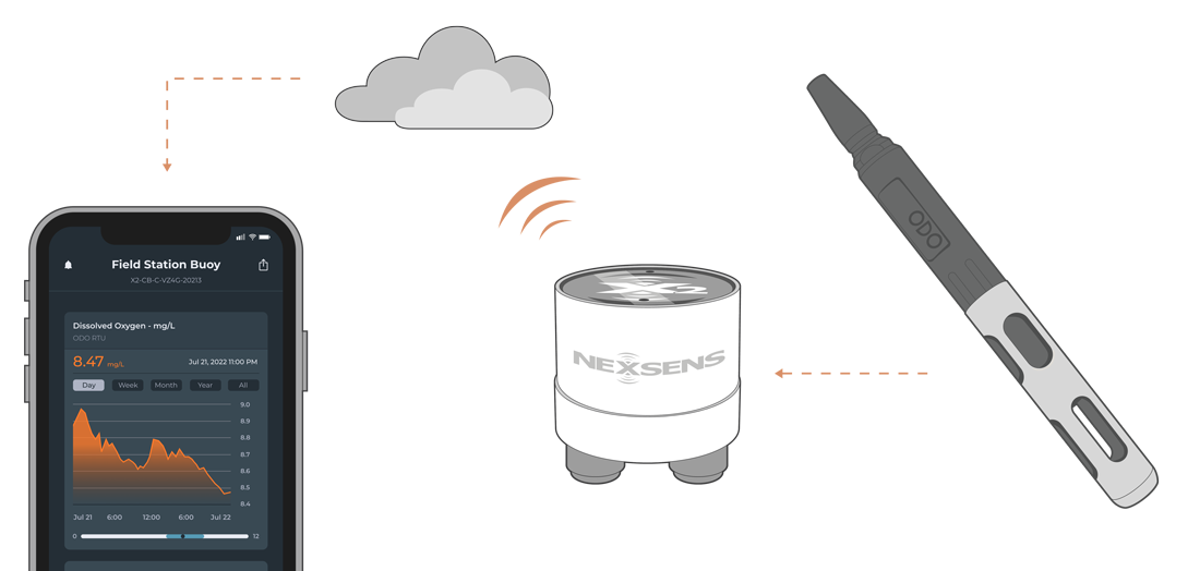
Figure 1: YSI ODO RTU Optical Dissolved Oxygen Sensor integration with NexSens X-Series data loggers.
Compatible Models
YSI currently offers a single model of the YSI ODO RTU, which comes with an optional conductivity sensor for automatic salinity compensation. The conductivity probe provides additional parameters such as conductivity (µS/cm), specific conductivity (µS/cm), salinity (ppt), conductivity nLF (µS/cm), and total dissolved solids (mg/L). Understanding the model and the number of available parameters is critical when creating the Modbus-RTU script.
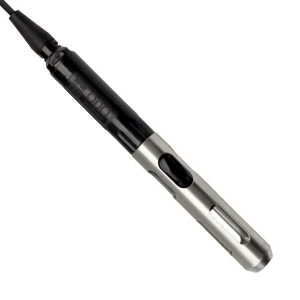
Figure 2: YSI ODO RTU Optical Dissolved Oxygen Sensor
Sensor Integration
Section 5 of the YSI ODO RTU manual outlines the Modbus configuration and commands necessary to create the Modbus-RTU script. The commands show the Modbus registers used to change the Modbus address and read from the available parameters. The sensor can be programmed using a NexSens RS-485 UW Sensor USB Adapter in any Modbus interface software.
1. Wiring for Communication
In nearly all applications involving NexSens integration, a connectorized UW8 plug will be added to the sensor cable, which is compatible with the NexSens RS-485 UW Sensor USB Adapter. However, users can wire the sensor using the flying leads for direct communication, or if a UW8 plug is added, the pins for the ground, power, and 485 communication are below.
| YSI ODO RTU Flying Lead Wire Color* | Signal | NexSens UW8 Plug Pins |
| Green/Drain Wire | Ground | 2 |
| Red | 12+VDC Power | 5 |
| White | RS-485 B | 7 |
| Black | RS-485 A | 8 |
2. Setting a Unique Modbus Address
The YSI ODO RTU does not require any changes to the internal settings before detecting with an X-Series data logger, except changing the sensor to have a unique Modbus address. A custom script must match the default internal settings for proper communication. For direct communication, the sensor has the following default communication parameters:
- Baud Rate: 9600
- Address: 1
- Parity: Even
- Stop bit: 1
- Data: 8-bit
Setting a Unique Modbus Address
If another sensor using Modbus-RTU communication is connected to the data logger, including additional YSI ODO RTU sensors, they will each need their own unique Modbus address. Below is the register information for adjusting the sensors’ Modbus address.
Read Current Modbus Address
| Function 0x03 (Read input registers) | |||
| Register | Data Type | Data Size | Purpose |
| 0x0000 | 16-bit Integer | 1 register | Requests the current Modbus address. |
Write a New Modbus Address*
| Function 0x06 (Write a Single Register) | |||
| Register | Data Type | Data Size | Purpose |
| 0x0000 | 16-bit Integer | 1 register | Writes a new Modbus address based on a user-entered value. |
*Power must be cycled on the sensor to solidify the new address.
3. Automatic Sensor Detection
After setting a unique Modbus address, a script can be generated to read the available parameters from the sensor.
X-Series Logger Detection and Script Information
During NexSens integration, a 4000-level script will be added to the X-Series data logger before shipment. If the sensor is purchased separately, contact NexSens to procure the script or create the script using the Generic Modbus Script Utility.
Note: While generating the script, the selected parameters must be a continuous register request. Thus, the script should begin with ODO saturation at register 0 and be in the order in the table below until the final parameter. Gaps in the register request will return erroneous data.
Sensor Parameters
The sensor outputs the dissolved oxygen and temperature parameters by default. Adding the optional conductivity sensor will add conductivity (µS/cm), specific conductivity (µS/cm), salinity (ppt), conductivity nLF (µS/cm), and total dissolved solids (mg/L). The manufacturer and model for the sensor are available within the script utility, which displays the default dissolved oxygen and temperature parameters. Choose Show all next to Available parameters to add the remaining conductivity sensors.
All parameters in the table below are 32-bit IEEE-754 floating point numbers in big-endian format. Each value is a combination of two registers. Values are read using a read input registers command (function code 0x04).
| CONNECT Parameter Name | Default Units | ODO RTU Parameter | Starting Register |
| DOSat | % | ODO Saturation | 0x0000 |
| DO | mg/L | ODO | 0x0002 |
| DOSat | % | ODO Local Barometer Compensated | 0x0004 |
| Temperature | °C | Temperature | 0x0006 |
| Temperature2 | °C | Reference Temperature | 0x0008 |
| Generic | ms | Time Since Boot* | 0x000A** |
| Conductivity | µS/cm | Conductivity | 0x000C |
| Sp Cond | µS/cm | Specific Conductivity | 0x000E |
| Salinity | ppt | Salinity | 0x0010 |
| nLF Cond | µS/cm | Conductivity nLF | 0x0012 |
| TDS | mg/L | Total Dissolved Solids | 0x0014 |
*The Time Since Boot parameter is an unsigned 32-bit integer.
**Only add parameters beyond Generic, if the optional conductivity probe is included on the sensor.
Run the Sensor Detection
Once the script is created, transfer and enable it on the data logger.
After the script is enabled, run a sensor detection to program the sensor onto the logger.
Read Sensor Configuration – Confirm Sensor Detection
After ~5-10 minutes, read the sensor configuration to confirm the YSI ODO RTU and other sensors have been detected on the data logger. Thoroughly review the parameter list to ensure all parameters are accounted for and are measured in the desired units. Let the unit gather a few readings to confirm accurate and reasonable parameter data.
Calibration Utility in the CONNECT Software
Utilize the YSI ODO RTU calibration utility in CONNECT to enter calibration coefficients and directly calibrate both dissolved oxygen and conductivity. Calibration coefficients are located on the “YSI ODO Sensor Cap Instruction Sheet” included with the new sensor cap. Once entering the coefficients, the user will need to perform a 1-point DO calibration within the utility. Additionally, it is recommended to perform a 1-point conductivity calibration before deployment.
Connect Directly to the ODO RTU Sensor
- Download and launch the CONNECT Software.
- Connect the included USB cable between the PC and the YSI ODO RTU sensor.
- Locate the Properties window, then select the proper COM Port for the cable from the Comm Settings tab on the far right.
- Set the following:
- Baud = 9600
- Frame = E81
- MBAddr = 1 (Default address is 1; however, enter the appropriate address if it has been changed).
- Set the following:
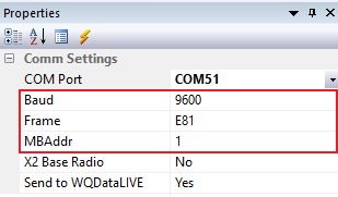
Figure 1: COM port properties.
- Provide 12VDC power to the YSI ODO RTU sensor.
- Go to Tool | Sensor | YSI ODO RTU.
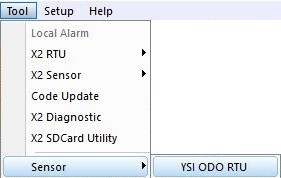
Figure 2: YSI ODO RTU utility location. |
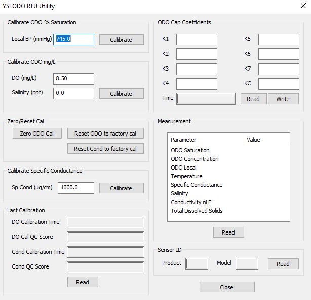
Figure 3: YSI ODO RTU calibration utility. |
Perform Conductivity Calibration
- Reference the Calibration – Conductivity section 3.2 (page 7) in the manual at the following link to properly set up the sensor for calibration.
- Select the appropriate calibration standard for the conductivity of the sampling environment.
- Enter this value in the available field, wait for the sensor to stabilize in solution, then click Calibrate .
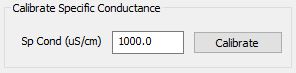
Figure 4: Insert conductivity standard solution concentration in the available field.
Note: The available options allow for factory reset of all calibrations if necessary.
Insert DO Cap Coefficients and Calibrate DO
- Using information from the “YSI ODO Sensor Cap Instruction Sheet”, insert the calibration coefficients into the box next to their corresponding ‘K’ values.
- Read the coefficients before writing the new values.
- Double-check all values and then press Send Coefficients.
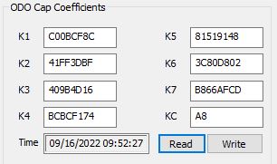
Figure 5: New ODO cap coefficients.
- YSI recommends performing a 1-point DO calibration once installing a new sensor cap. Follow the Calibration – Dissolved Oxygen section 3.3 (page 8) in the manual link below to properly set up the sensor for calibration.
- For dissolved oxygen calibrations:
- If calibrating ODO % saturation, enter the local barometric pressure in mmHg using a 3rd party sensor. Click Calibrate after allowing the sensor to stabilize in solution.
- Note: The barometric pressure by a local weather forecast is sea-level corrected, and thus, cannot be used.
- If calibrating ODO mg/L, enter the known DO standard in mg/L and the known salinity value. Click Calibrate after allowing the sensor to stabilize in solution.
- Note: The calibration ignores the salinity value input if the ODO RTU includes a conductivity sensor.
- If performing a zero standard calibration, click Calibrate after allowing the sensor to stabilize in solution.
- If calibrating ODO % saturation, enter the local barometric pressure in mmHg using a 3rd party sensor. Click Calibrate after allowing the sensor to stabilize in solution.
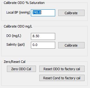
Figure 6: ODO sensor calibration options.
Note: The available options allow for factory reset of all calibrations if necessary.
Read Last Calibration Time and Live Measurement
Once performing a calibration, the sensor provides the latest calibration time and the QC score. There are three potential responses for the QC score:
- 0 (Best)
- This indicates proper sensor calibration and that all performance-related parameters meet factory-defined limits.
- 1 (OK)
- The sensor is still performing within factory-defined limits. However, during calibration, the required adjustment suggests significant sensor drift potentially requiring further maintenance, such as a new DO cap.
- 2 (Bad)
- The sensor is not performing within factory-specified limits. In some cases, a bad QC Score might indicate that a component of the sensor is due for replacement (such as a DO cap). Exceedance of a user-defined limit is another possibility, for example, an expired term since the most recent calibration.
Note: Once calibrations are complete, it is recommended to read a direct measurement value from the sensor in the standard solutions.
4. Setting up WQData LIVE
Once an X-Series data logger has finished a new sensor detection, it will automatically push the sensor configuration to the WQData LIVE Web Datacenter. Follow the three articles below to create a WQData LIVE account and a project/site. Then add the data logger to the project using the included claim code.
- Create a WQData LIVE Account
- Create a Project on WQData LIVE
- Add a Data Logger to a Project on WQData LIVE
Real-Time System Application
Real-time DO measurements from YSI ODO RTU sensors are useful in various environmental monitoring applications.
Applicable Systems
Discover applicable uses for YSI ODO RTU sensors.
- Dissolved Oxygen Monitoring Systems
- Inland Lake Monitoring Systems
- Stream and River Monitoring Systems
Dissolved Oxygen Measurements
Learn more about dissolved oxygen measurements on the NexSens Blog Page. Blog posts specifically regarding DO monitoring systems are below:
- Best Dissolved Oxygen Sensors
- Dissolved Oxygen Monitoring Systems
- Dissolved Oxygen Monitoring at Hydroelectric Plants: Part I
- Dissolved Oxygen Monitoring at Hydroelectric Plants: Part II
Sensor Manual
For additional information on the YSI ODO RTU sensor, please refer to the Sensor Manual.