
The log start time and selective upload interval(s) can be set through the Advanced Device Remote Configuration tool. These features allow the X2 to log data to its internal memory at a specific log start time and control the transmission of certain parameters. These features help reduce system data usage and telemetry on-time. Adjust […]
Articles Tagged: Knowledge Base
Tag new knowledge base for search
Update Data Logger Settings
For proper transmission, the internal data logger settings must match the settings on WQData LIVE. Multiple commands will achieve this purpose depending on the telemetry model of the logger. Both commands can be accessed from the Advanced Device Remove Configuration Tool within the administrator settings. The Sync settings command applies to Wifi and cellular telemetry […]
Accessing the Advanced Device Remote Configuration Tool
The Advanced Device Remote Configuration tool allows the user to adjust the following: Update data logger settings Set the log and transmit start times Change which parameters are logged and transmitted Change the data logger transmission settings To access the tool: Navigate to the ADMIN | Settings tab found at the top of the project Dashboard. […]
Averaging Logged Sensor Data
Averaging for sensor parameters may be enabled by adjusting the log and sample intervals in the Device Remote Configuration Tool within the administrator settings. Log Interval: Frequency of data written to the data logger memory to be transmitted to the web. Sample Interval: Frequency of data read from the sensor by the data logger internally. […]
Accessing the Device Remote Configuration Tool
The Device Remote Configuration Tool allows remote configuration of the following: Change sensor logging and transmit intervals Configure event based transmissions for G2 and V2 systems Choose which parameters are logged and transmitted to the web Configure parameter offsets Name a data logger Run a sensor detection Sync X2 data logger settings To access […]
What is the X2-SDLMC sensor port layout?
The X2-SDLMC sensor ports are labeled to outline the Universal Asynchronous Receiver Transmitters (UARTs) available on the data logger. The sensor ports on the logger are engraved with Sensor 1 and Sensor 2. These ports correspond to the traditional P0 (Sensor 1) and P1 (Sensor 2) ports on other X2 data logger models.
What is the X2-CBMC sensor port layout?
The X2-CBMC sensor ports are labeled to outline the (4) Universal Asynchronous Receiver Transmitters (UARTs) available on the data logger. These locations are critical to note for sensor detections; however, harsh deployment conditions may remove these labels. The following schematic outlines the sensor port’s location in relation to the vent, antenna, and 6-pin solar/com port. […]
What is the X2-CB sensor port layout?
The X2-CB sensor ports are labeled to outline the (4) Universal Asynchronous Receiver Transmitters (UARTs) available on the data logger. These locations are critical to note for sensor detections; however, harsh deployment conditions may remove these labels. The following schematic outlines the sensor port’s location in relation to the vent, antenna, and 6-pin solar/com port. […]
What sensor interfaces are on an X-Series Data Logger?
There are 4 Universal Asynchronous Receiver Transmitters (UARTs) on an X2 and 3 UARTs on an X3 data logger. (1) Dedicated RS-485 channel that is available on all ports. RS-485 channel supports baud rates up to 57600. (1) Dedicated SDI-12 channel that is available on all ports. For X2 Logger (2) Dedicated RS-232 channels on […]
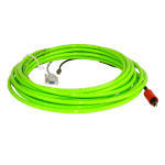
Use a Terminal Emulator to Configure a Nortek Sensor
If unable to access the Nortek software, configuration settings required to interface the Signature with the X2 may be adjusted through a third party terminal emulator such as TeraTerm. Double-check the telemetry and cell configuration deployment settings through the third party terminal emulator and make changes where required. Connect the 8-pin MCIL plug of the […]