
YSI Nile Radar Water Level Sensor X-Series Integration Guide
Real-Time Water Level Measurements
The YSI Nile Radar Water Level Sensor provides non-contact, continuous level measurements. The sensor is compatible with NexSens X-Series data loggers using the SDI-12 communication protocol and sensor interface. A pre-defined script on X-Series data loggers is able to detect, log, and transmit all measurement parameters. Parameter data is transmitted, in real-time, at a user-specified interval (e.g., 10 minutes) to the NexSens WQData LIVE Web Datacenter. There, data is stored on customizable dashboards with statistics and graphical interfaces for each parameter. Users can download and send data reports via Email, FTP, or an API. Below is information on the settings and wiring required to integrate these sensors with a NexSens X-Series data logger.

Figure 1: YSI Nile Radar Sensor integration with NexSens X-Series data loggers for real-time water level measurements.
Compatible Models
The Nile Radar Series uses a downward looking microwave transmitter to send and receive radar signals. The signal is reflected by the medium (i.e., water level surface) and received through its horn antenna, where the change in frequency is proportional to the distance and is converted into the level or stage measurement.
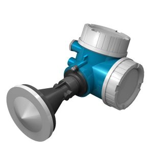
Figure 2: YSI Nile 502/504 Water Level Sensor. |
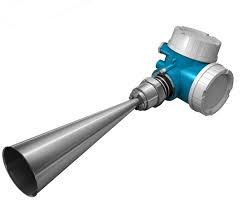
Figure 3: YSI Nile 517 Water Level Sensor. |
Nile Radar Water Level Sensor Integration
Accurate level readings from the Nile Radar Water Level sensor rely on an accurate initial stage reference between the location of the sensor’s antenna and the bottom of the measured medium (i.e., bottom of a river, channel, lake, etc.). The sensor is designed to read the distance between its antenna and the top of the measured medium (i.e., water level surface). The user-specified stage reference will then provide the offset to calculate the overall water level between the bottom and top of the medium (i.e., water level/stage). The stage reference setting can be set through the CONNECT software SDI-12 utility via a direct connection.
1. Wiring
In nearly all applications involving NexSens integration, a connectorized UW8 plug will be added to the sensor cable. However, other applications may require a UW8 to flying lead cable utilized for wiring the sensor and cable into an external junction box. The following table provides information for both applications.
| NexSens UW8 Plug Pin | NexSens UW8-FLx Wire Color* | Signal | YSI H-SDI-CABLE-x Wire Color |
| 2 | Black | Ground | Black/Green |
| 5 | Red | 12V Power | Red |
| 6 | Brown | SDI-12 | White |
*NexSens UW Plug to Flying Lead Cable
2. Configure the Stage Reference
For accurate stage readings, this reference level will need to be adjusted to reflect the overall distance between the sensor and the bottom of the measured medium (i.e., bottom of a river, channel, lake, etc.). Stage reference level adjustments can be made via direct SDI-12 communication through the data logger. The steps below outline how to use CONNECT’s SDI-12 communication utility to make adjustments to the internal settings on the sensor.
The commands below outline how to write the stage reference values for the final deployment location.
Write Stage Reference
| Command | Response | Description |
| aXSCS<value>! | a<value><CR><LF> | a: sensor address <value>: (Ex: 10.0) <CR><LF> |
3. Automatic Sensor Detection
After setting the stage reference level, the sensor and its parameters can be programmed onto the logger via automatic detection.
X2 Script Information
During NexSens integration, a 4000-level script will be added to the X-Series data logger before shipment. If the sensor is purchased separately, contact NexSens to procure the script or create the script using the SDI-12 Script Utility.
Sensor Parameters
The sensor outputs the following parameters.
| CONNECT Parameter Name | Default Units | Nile Sensor Parameter Name |
Description |
| Stage | m | Current Stage Level | Stage/Level based on measured distance value and calculation with user-defined stage reference. |
| Level | m | Distance to Reflected Surface | Distance between sensor antenna and the surface of the measured medium (i.e., water surface). |
| Battery | V | Battery Voltage | — |
Run the Sensor Detection
Once the script is created, transfer and enable it on the data logger.
After the script is enabled, run a sensor detection to program the sensor onto the logger.
Read Sensor Configuration – Confirm Sensor Detection
After ~5-10 minutes, read the sensor configuration to confirm the Radar and other sensors have been detected on the data logger. Thoroughly review the parameter list to ensure all parameters are accounted for and are measured in the desired units. Let the unit gather a few readings to confirm accurate and reasonable parameter data.
4. Setting up WQData LIVE
Once an X-Series data logger has finished a new sensor detection, it will automatically push the sensor configuration to the WQData LIVE Web Datacenter. Follow the three articles below to create a WQData LIVE account and a project/site. Then add the data logger to the project using the included claim code.
- Create a WQData LIVE Account
- Create a Project on WQData LIVE
- Add a Data Logger to a Project on WQData LIVE
Real-Time System Application
Real-time water level measurements from the YSI Nile Radar Water Level Sensor are useful in various environmental monitoring applications.
Applicable Systems
Discover applicable uses for the YSI Nile Radar Water Level Sensor.
For additional information, please reference the YSI Nile Radar Water Level Sensor Manual.