
OTT SVR 100 X-Series Integration Guide
The OTT SVR 100 Surface Velocity Radar Sensor is designed for measuring flow in open channels and rivers. The sensor is compatible with NexSens X-Series data loggers utilizing the SDI-12 communication protocol and sensor interface. Parameter data is transmitted, in real-time, at a user-specified interval (e.g., 10 minutes) to the NexSens WQData LIVE Web Datacenter. There, data is stored on customizable dashboards with statistics and graphical interfaces for each parameter. Users can download and send data reports via Email, FTP, or an API. Below is information on the settings and wiring required to integrate OTT SVR 100 Surface Velocity Radar Sensors with NexSens X-Series data loggers.
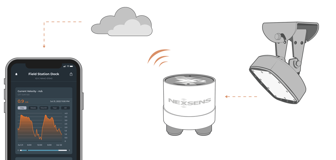
Figure 1: OTT SVR 100 Surface Velocity Radar Sensor integration with NexSens X-Series data loggers.
Compatible Models
OTT provides a single model of the SVR100 that is compatible with NexSens X-Series data loggers. Measurements collected by the sensor are based on the physical Doppler effect. A radar pulse is emitted at a 24.2 GHz frequency and is reflected from particles moving on the water’s surface. If the water is moving, the radar pulses are reflected with a slight frequency shift that can then be calculated as the surface velocity.
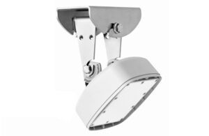
Figure 2: OTT SVR 100 Surface Water Velocity Radar Sensor
Sensor Integration
Using the CONNECT software, a generic SDI-12 script can be generated to provide communication between the logger and sensor at a user-specified interval. The only settings that may require adjust is the SDI-12 address to ensure it is unique from all other connected sensors.
1. Wiring
NexSens can provide a connectorized UW8 plug on the end of the OTT SVR 100 factory cable for integration with an X-Series data logger, or a UW8 to flying lead cable may be utilized for wiring into a junction box. The following table refers to the latter application.
| NexSens UW8 Plug Pin | NexSens UW8-FLx Wire Color* | Signal | OTT Sensor Cable Wire Color |
| 2 | Black | Ground | Grey & White |
| 5 | Red | 12V Power | Brown |
| 6 | Brown | SDI-12 | Red |
*NexSens UW Plug to Flying Lead Cable
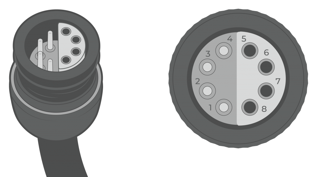
Figure 3: NexSens UW8 Plug pin numbers.
2. Configure Communication
An RS-232 USB cable with a separate external power source may be utilized for communication with the OTT SVR 100 sensor in the OTT SVR 100 Operating Program. Default SDI-12 settings do not need to be changed for communication with the X-Series data logger. This operating program allows for viewing real-time data and changing the following settings:
- Device SDI-12 address
- Filter Type
- Filter Length
- Radar Sensitivity
- Flow Direction Filter
| NexSens RS-232 USB Cable Wire Color | Signal | OTT Sensor Cable Wire Color |
| Yellow | RS-232 Tx | Green |
| Orange | RS-232 Rx | Yellow |
| Black | Ground | White & Grey |
| –* | +9…+27VDC | Brown** |
*No external power source should be connected to the USB cable.
**An external power source must be utilized to provide between 9-27VDC to the sensor. Ensure that the external power source has a common ground with the USB cable and OTT sensor cable.
3. Automatic Sensor Detection
The user must create a Generic SDI-12 script through the NexSens CONNECT software to communicate and gather measurements from the sensor. The user must reference the SDI-12 address and parameters output by the sensor for proper configuration. Follow the link below to review the process for creating a Generic SDI-12 script through the CONNECT Software:
SDI-12 Script Generation
The Generic manufacturer and SDI-12 model must be selected in the SDI-12 script utility. The measurement command should always be ‘C’, which allows for measurements to be obtained concurrently with other SDI-12 sensors connected to the logger. Switch power provides a balance between power consumption and data accuracy. SDI-12 sensors require a specific warmup time depending on the number of parameters to be measured. Determine the appropriate warmup time by communicating with the sensor in the CONNECT SDI-12 Tool:
| Manufacturer | Model | SDI-12 Address | Port | Warmup | Measurement Command | Power |
| Generic | SDI-12 | 0-9 (Default = 0) | P0, P1, or P2 | At least 5 seconds longer than the sample duration | C | Switch |
Parameter List from C Command
The default parameter list for the sensor is below. Match the parameter output below in the script.
| CONNECT Parameter Name | Units | OTT SVR 100 Parameter Name |
Description |
| Velocity | m/s | Mean Velocity of Flow | Average flow velocity over approximately 30 seconds. |
| Velocity | m/s | Current Velocity of Flow | Current flow velocity. |
| Parm 01 | deg | Sensor Tilt Angle | Inclination relative to the water surface. Optimal range is between 30 and 45 degrees. |
| Parm 02 | — | Signal Quality Index | Quality of radar signal received for measurement.
0 – Good Signal |
| Parm 03 | — | Vibration Index | Measure of vibrations in deployment area.
0 – No vibration |
| SNR | dB | Signal-to-Noise Ratio | Measure of desired radar signal to the level of background noise.
>6 – Good signal |
Run the Sensor Detection
Once the script is created, transfer and enable it on the data logger.
After the script is enabled, run a sensor detection to program the sensor onto the logger.
Read Sensor Configuration – Confirm Sensor Detection
After ~5-10 minutes, read the sensor configuration to confirm the sensors have been detected on the data logger. Thoroughly review the parameter list to ensure all parameters are accounted for and are measured in the desired units. Let the unit gather a few readings to confirm accurate and reasonable parameter data.
4. Setting up WQData LIVE
Once an X-Series data logger has finished a new sensor detection, it will automatically push the sensor configuration to the WQData LIVE Web Datacenter. Follow the three articles below to create a WQData LIVE account and a project/site. Then add the data logger to the project using the included claim code.
- Create a WQData LIVE Account
- Create a Project on WQData LIVE
- Add a Data Logger to a Project on WQData LIVE
Real-Time System Application
Real-time surface velocity measurements from the OTT SVR 100 Surface Velocity Radar Sensor are useful in various environmental monitoring applications.
Applicable Systems
Discover applicable uses for the OTT SVR 100 Surface Velocity Radar Sensor.
Case Studies
Read about specific applications using the OTT SVR 100 Surface Velocity Radar Sensor.
Sensor Manual
For additional information on the OTT SVR 100 Surface Velocity Radar Sensor, please refer to the OTT SVR 100 Surface Velocity Radar Sensor Manual.