
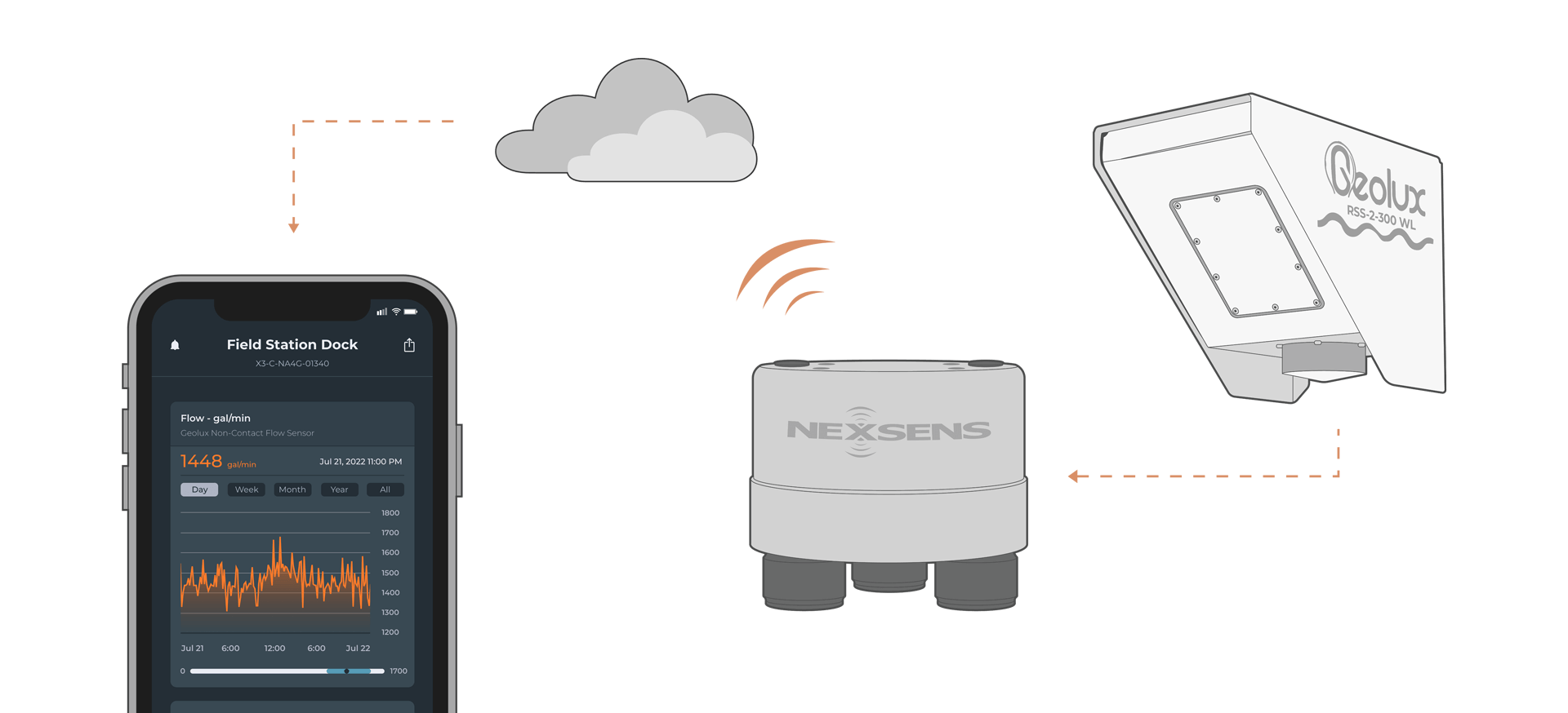
Geolux Non-Contact Flow Sensor X-Series Integration Guide
The Geolux Non-Contact Flow Sensor measures flow using non-contact radar technology. It easily integrates with NexSens X-Series data loggers using the SDI-12 sensor interface.
Sensor Setup
Follow the manufacturer’s guidelines for sensor setup, ensuring that the sensor is in SDI-12 automatic sleep mode.
Note: Be sure to document the SDI-12 address
Connecting with X-Series Loggers
Next, the sensor will need to be set up for the X-Series logger using CONNECT software. If you have not yet done so, set up the project in WQData LIVE.
- Connect the sensor using the supplied cable to one of the open sensor ports on the logger and note the port number.
- Plug the X3 into the USB port of the computer and power it on with the AC power cable.
- Open CONNECT and select the SENSOR tab.
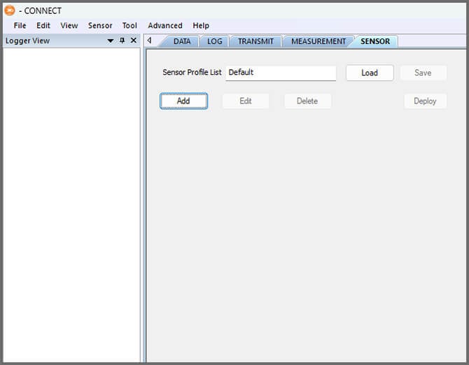
- Click Add and select Geolux from the Manufacturer drop-down. Then select the appropriate model.
- Adjust the SDI-12 address if needed and select the port number.
- Select either Continuous or Switch in the Power drop-down.
- Switch is recommended.
- Add or remove sensor parameters as desired.
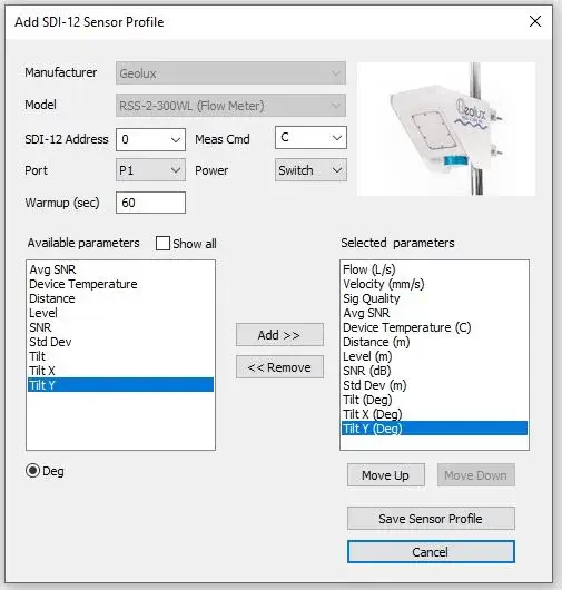
- Select Save Sensor Profile.
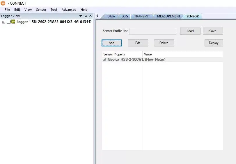
- Complete the setup for all other sensors, and then click Save.
- Name the Sensor Profile List and select Ok.

- Complete system setup by clicking Deploy.
- Confirm that data is being transferred to WQData LIVE at the next interval (default is 10 minutes).
Mounting
The Geolux Non-Contact Flow Sensor can be deployed on docks, bridges, and other nearshore environments. For mounting instructions, follow manufacturer guidelines.