
Real-Time Water Level Measurements
The VegaPuls C 23 Radar Water Level Sensor provides non-contact, continuous level measurements. The sensor is compatible with NexSens X-Series data loggers using the SDI-12 communication protocol and sensor interface. A pre-defined script on X-Series data loggers is able to detect, log, and transmit all measurement parameters. Parameter data is transmitted, in real-time, at a user-specified interval (e.g., 10 minutes) to the NexSens WQData LIVE Web Datacenter. There, data is stored on customizable dashboards with statistics and graphical interfaces for each parameter. Users can download and send data reports via Email, FTP, or an API. Below is information on the settings and wiring required to integrate these sensors with a NexSens X-Series data logger.
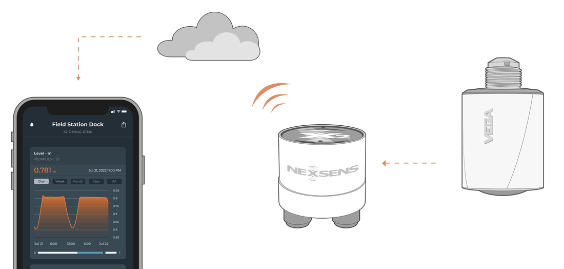
Figure 1: VegaPuls C 23 Radar Water Level Sensor integration with NexSens X-Series data loggers.
Compatible Models
The VegaPuls C 23 uses a continuous, frequency-modulated radar signal for water level measurements. The signal is reflected by the medium (i.e., water level surface) and received through its antenna, where the change in frequency is proportional to the distance and is converted into the level or stage measurement.
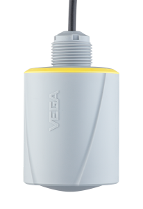
Figure 2: VegaPuls C 23 Radar Level Sensor
VegaPuls C 23 Sensor Integration
Accurate level readings from the VegaPuls C 23 sensor depend on an accurate stage reference, which can be configured via the VEGA Tools app with power provided by the NexSens data logger.
1. Wiring
In nearly all applications involving NexSens integration, a connectorized UW8 plug will be added to the sensor cable. However, other applications may require a UW8 to flying lead cable utilized for wiring the sensor and cable into an external junction box. The following table provides information for both applications.
| NexSens UW8 Plug Pin | NexSens UW8-FLx Wire Color* | Signal | VegaPuls C 23 Cable Wire Color |
| 2 | Black | Ground | Blue & Drain Wire |
| 5 | Red | 12V Power | Brown |
| 6 | Brown | SDI-12 | White |
*NexSens UW Plug to Flying Lead Cable
2. Automatic Sensor Detection
A new sensor profile must be created for the VegaPuls sensor.
- Download the latest version of CONNECT. Connect the logger to a PC and launch CONNECT.
- On the Config tab, click the drop-down arrow to the right of the Create Script button and select Generic SDI-12.
- The Script Utility menu will appear.
- Under Manufacturer, select Generic.
- Under Model, select SDI-12.
- SDI-12 Address – Enter the sensor’s SDI-12 address. Each sensor must have a unique address for proper communication.
- Measurement Command (Meas Cmd) – The measurement command should always be ‘C,’ which allows measurements to be obtained concurrently with other SDI-12 sensors connected to the logger.
- Port – Select the data logger port the sensor will be connected to.
- Power – Select the power type required for the sensor.
- Switch – Turns on power to the listed sensor port at a specified period of time ahead of each scheduled reading. The sensor powers off once the logger collects data for the reading.
- The Warmup field determines how long the sensor will be powered in advance of each reading. See manufacturer guideline for details.
- Continuous – Power will be applied constantly.
- None – No power is applied to the port.
- Switch – Turns on power to the listed sensor port at a specified period of time ahead of each scheduled reading. The sensor powers off once the logger collects data for the reading.
- The sensor’s default parameter output is in the table below. Add parameters to the Selected Parameters column in the order shown below.
- Select Generate Script, assign a script number, and click OK to save the script in the CONNECT software folder.
- If creating multiple generic scripts for the X3, assign a unique value to each.
- If making modifications to an existing generic script, assign the same script number to overwrite the original.
| CONNECT Parameter Name | Default Units | VegaPuls C 23 Parameter Name |
Description |
| Stage | m | Stage | Stage/Level based on measured distance value and calculation with user-defined stage reference. |
| Level | m | Distance | Distance between sensor antenna and the surface of the measured medium (i.e., water surface). |
| Temperature | C | Temperature | Electronics temperature (For diagnostic purposes) |
| Parm01 | dB | Reliability* | Measurement reliability based on internal calculations. |
| Parm02 | — | Device Status | Review device status error codes on pages 55-57 of the manual. |
*The measurement reliability of the level echo curve is displayed as a dB value. The measurement reliability equals signal strength minus noise. The higher the value, the more reliable the measurement. With a functioning measurement, the values are typically > 9 dB.
Run the Sensor Detection
Once the script is created, transfer and enable it on the data logger.
After the script is enabled, run a sensor detection to program the sensor onto the logger.
NOTE: If additional sensors will be included in the system, be sure to follow their respective integration guides before running a sensor detection. All sensors must be fully configured and connected before starting a detection.
Read Sensor Configuration – Confirm Sensor Detection
After ~5-10 minutes, read the sensor configuration to confirm the VegaPuls and other sensors have been detected on the data logger. Thoroughly review the parameter list to ensure all parameters are accounted for and are measured in the desired units. Let the unit gather a few readings to confirm accurate and reasonable parameter data.
3. Setting up WQData LIVE
Once an X-Series data logger has finished a new sensor detection, it will automatically push the sensor configuration to the WQData LIVE Web Datacenter. Follow the three articles below to create a WQData LIVE account and a project/site. Then add the data logger to the project using the included claim code.
- Create a WQData LIVE Account
- Create a Project on WQData LIVE
- Add a Data Logger to a Project on WQData LIVE
4. Configure the Stage Reference
Setting the stage reference is typically performed in the field, unless the reference value is known beforehand. Power must be provided from the X-series data logger or a separate source.
- Download the VEGA Tools app on your PC or mobile device.
- Apply power to the sensor.
- For X2 data loggers, use the X2 Diagnostic Tool to provide power via one of the sensor ports (i.e., P0, P1 or P2).
- For X3 data loggers, port P0 provides continuous power.
Follow the VegaPuls C23 Operations Manual to set the stage reference value.