Instructions for interfacing the Vaisala PTB110 with a NexSens iSIC data logger:
IMPORTANT: Review the manufacturer’s manual for the sensor to ensure that the sensor is properly configured for integration with a third party data logger prior to connecting the device to the iSIC.
1. Route cables and wires through one of the gland fittings installed on the iSIC enclosure.
2. Unplug the green terminal strip from the iSIC before inserting sensor wiring. The left terminal strip is designated for digital inputs (RS-485, RS-232, SDI-12, etc.) ; the right for analog inputs (mV, 4-20 mA, etc.).
3. Figures 1-4 below show wiring for two different configurations of the PTB110 barometer. The PTB110 has a default output range of 0-5 VDC. Since the iSIC data logger can only accept up to a 0-2.5 VDC input, the range must be reduced with a voltage divider in this case. The voltage divider consists of a pair of 10 k-ohm resistors. See Figures 1 and 2 for the wiring.
The PTB110 barometer may also be scaled by the factory to reduce the output range to 0-2.5 VDC. In this case, the voltage divider is not required, and figures 3 and 4 should be reference for the wiring.
IMPORTANT: Verify that no wires are loose or clamped on the insulation as this will cause intermittent or failed communication. Seal and caulk the gland fitting to prevent moisture intrusion and maintain the NEMA4X rating of the iSIC enclosure.
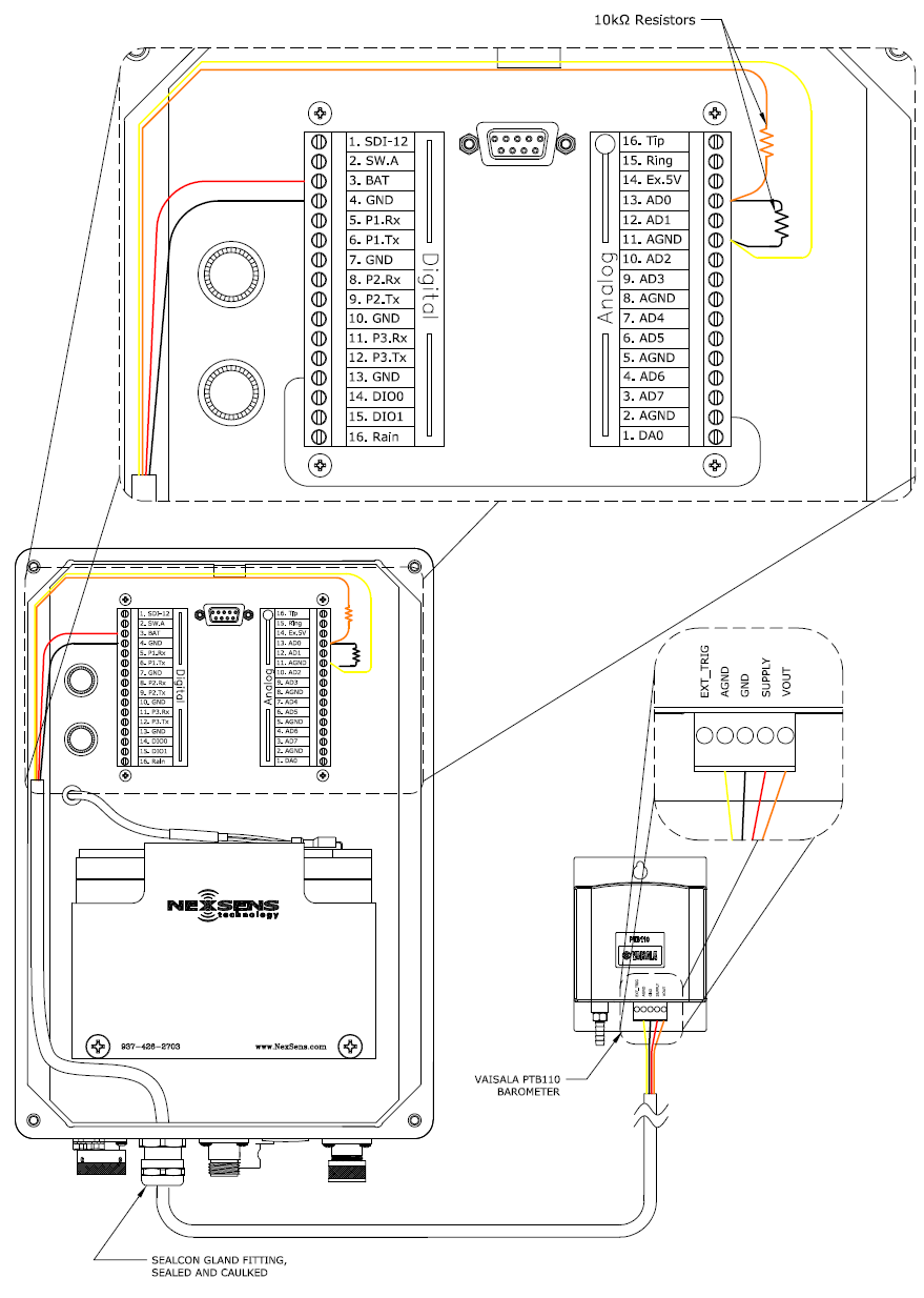
Figure 1: Wiring a Vaisala PTB110 (with 0-5 VDC Output) into an iSIC Data Logger.
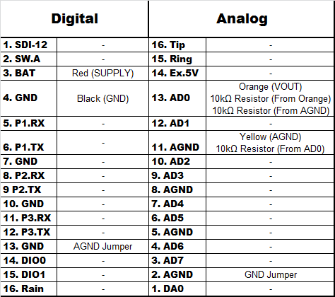
Figure 2: Table for wiring a Vaisala PTB110 (with 0-5 VDC Output) to an iSIC Data Logger.
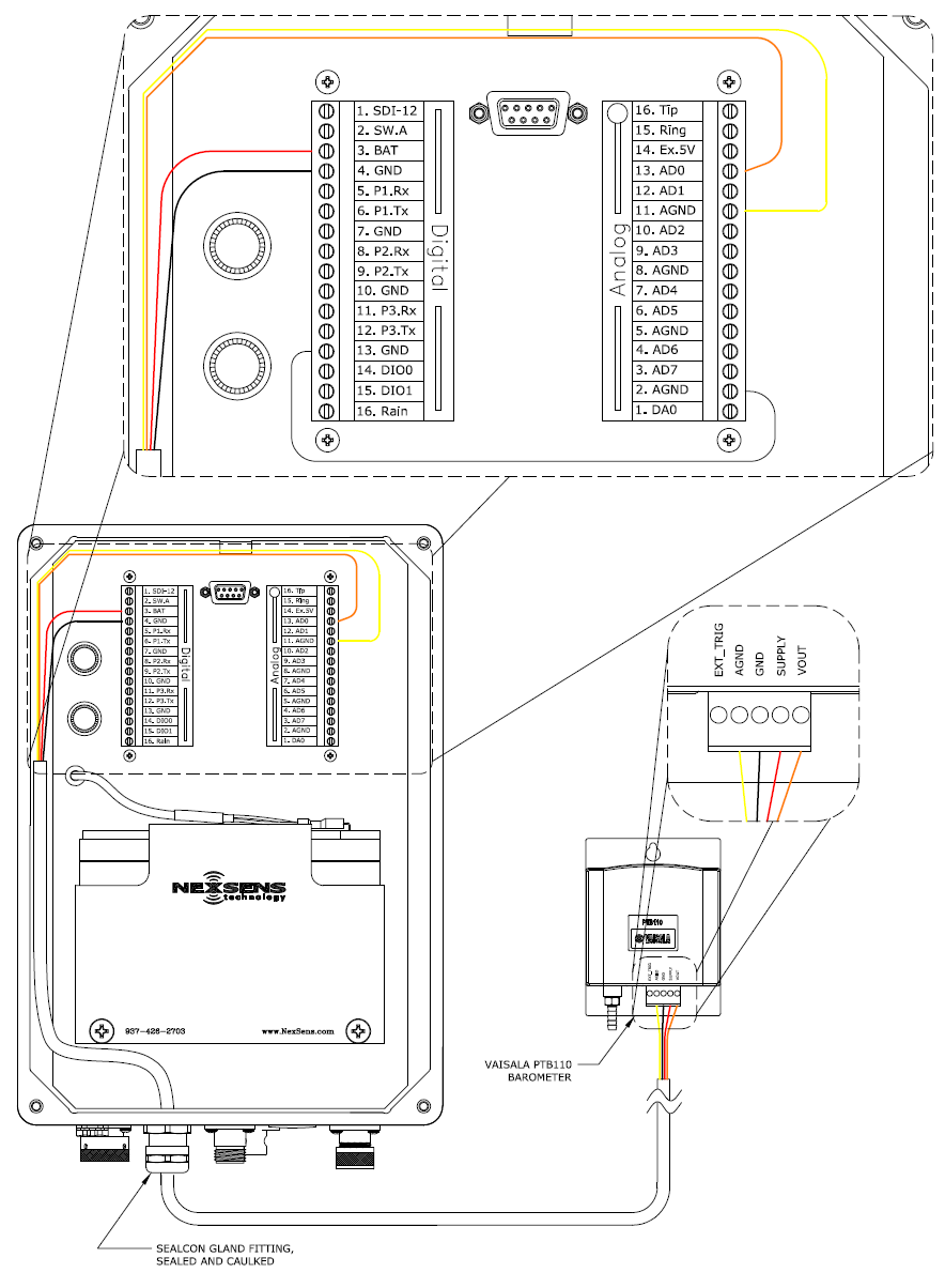
Figure 3: Wiring a Vaisala PTB110 (with 0-2.5 VDC Output) into an iSIC Data Logger.
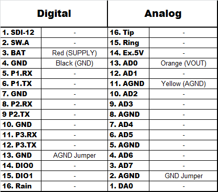
Figure 4: Table for wiring a Vaisala PTB110 (with 0-2.5 VDC Output) to an iSIC Data Logger.
4. Add the Device through the iChart Setup Device Wizard, and refer to the iChart Knowledge Base for additional information and troubleshooting.
REV: 14L25