
Parameter alarms configured on the iSIC data logger allow users to setup and configure controls to do things such as flash warning lights, trigger ISCO samplers, etc. The iSIC allows two kinds of control, 3.3V digital I/O and 12V 100mA switches. These can be accessed via the Setup Device Wizard in iChart. This may be accessed when first setting up a project or by clicking Project | Setup Device Wizard.
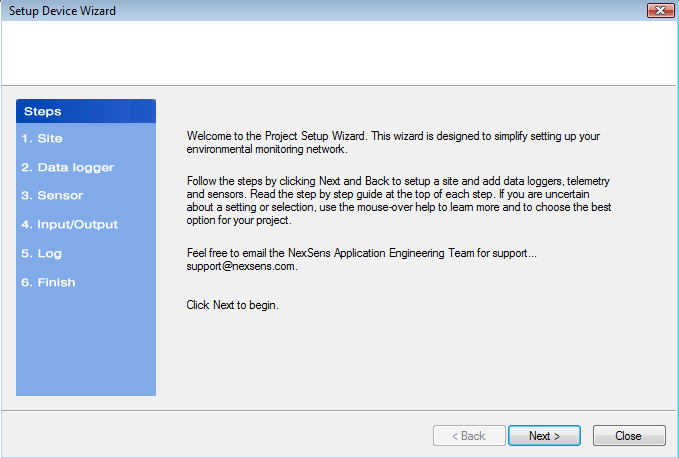
Figure 1: Setup Device Wizard
Proceed through the Setup Device Wizard as needed. Step 4 allows for entering control outputs.

Figure 2: Step 4 of Setup Device Wizard, Input/Output
On the Input/Output tab of the Setup Device Wizard, iSIC alarm controls can be configured. Select the data logger to be configured and click the Add button under Control Output. The Define iSIC Output Control window will appear.

Figure 3: Define iSIC Output Control window
Place a check in the Enable iSIC Output Control box and give it a name. This name will be used when identifying this control. Click the Add button to open the iSIC Control Output Condition window.

Figure 4: iSIC Control Output Condition window
A control condition is checked by the data logger every sample interval. To set up a condition:
1. Pick a parameter from the drop down list.
2. Select a parameter condition (such as greater than or less than) as well as a parameter value and count (see below).
The Count is the number of times the condition has to occur before the alarm actions will occur. The count is based on the data logger sample interval. For example, if the sample interval is 5 minutes and the count is 3, the alarm action would occur after 15 minutes of the alarm
condition. This feature is useful to prevent data spikes from causing alarm actions, such as turbidity jumping to a large value due to a leaf floating by, etc.
Click OK and then click Edit in the Control Output section to open the iSIC Control Output Action dialog box.
Select the Action and Channel to perform the alarm on. The options are either 3.3V DIO or 12V, 100mA switches. The DIO.0 and DIO.1 pins on the iSIC Digital terminal strip are the 3.3V controls, and the SW.A pin is the 12V, 100mA control.

Figure 5: Define iSIC Output Control with example Control Parameter
Click OK and finish the Setup Device Wizard to complete the setup.
REV: 15F03