
Digital I/O uses a voltage signal to represent either a one or a zero. A “0” typically ranges from 0 volts to 0.8 volts while a “1” will range from 2.4 volts to 5 volts. These ranges are defined in the TTL (Transistor-Transistor Logic) specification.

Figure 1: Digital Input – Output Device
Environmental data loggers can use digital I/O ports for a variety of applications. A digital output from a data logger may be used to control a relay that turns on a light, alarm, or activates a pump. A level switch with digital outputs can interface directly with a data logger to detect changes in level. For example, if water level drops below a set point, the switch output changes from “0” to “1” thus notifying the data logger of a low level.
Advanced DIO Options
When testing DIO functionality, it is sometimes required to view the current state or change the state of a DIO. For example, when connecting an auto sampler it is recommended to manually pulse the signal to make sure all of the wiring is correct, and the sampler will activate when a control output condition occurs. To do this in iChart, go to the Advanced | iSIC | iSIC menu.
The iSIC Setup dialog box will open:
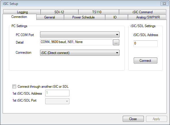
Figure 1: iSIC Setup window
The first screen gives the iSIC connection options. Enter the COM port and connection method of the desired iSIC as well as the iSIC Address. For example, if trying to connect to a 2100-iSIC with a modem connected to COM3, select 2100-iSIC from the connection drop down menu and COM3 from the COM port menu. The iSIC Address will typically be “1” unless changed by the user. When this information has been correctly entered, click the Connect button.
After connecting, click on the IO tab. The current DIO and tip status will be displayed. If the DIO pin is configured as an input in the Project | Setup Device Wizard, it will be grayed out and show the current status. If the DIO pin is configured as an output, it will allow for changing the status by selecting a new value and placing a check in the Change check box.

Figure 2: IO tab
Note: DIO manual status changes will automatically change back to the DIO normal operating condition at the next sample interval, or the top of every hour, whichever comes first.
REV: 13G02