
Nortek Aquadopp 2.0 X2 Integration Guide
Real-Time Current Profiling
The second generation of Nortek Aquadopp Current Profilers are compatible with NexSens X-Series data loggers via the Modbus-RTU communication protocol and the RS-232 sensor interface. Parameter data is transmitted, in real-time, at a user-specified interval (e.g., 10 minutes) to the NexSens WQData LIVE Web Datacenter. There, data is stored on customizable dashboards with statistics and graphical interfaces for each parameter. Users can download and send data reports via Email, FTP, or an API. Below is information on the settings required to integrate these sensors with a NexSens X-Series data logger.

Figure 1: Nortek Aquadopp 2.0 integration with NexSens X-Series data loggers for real-time current profiling measurements.
Compatible Models
Nortek provides multiple models of the Aquadopp Current Profilers with varying ranges and features. All are compaible with NexSens X-Series data loggers as long as the native output is via the RS-232 sensor interface.
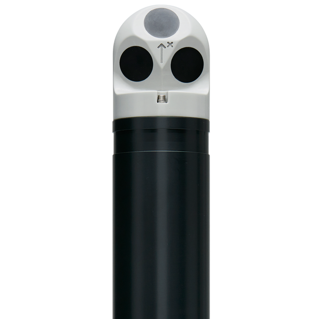
Figure 2: Notek Aquadopp 1 MHz Current Profiler.
Aquadopp Integration
Nortek’s Deployment software must be used to configure a second generation Aquadopp. Most of the deployment settings can be set in the software; however, communication settings must be updated using a terminal program.
Communication Setup

Figure 3: Nortek Deployment software.
- Connect the Nortek-supplied communications cable to the PC and supply power.
- Select CONNECT and choose the corresponding COM port. Keep the baud rate at 115200 for new device connections.
- Click CONNECT at the bottom of the interface and the Aquadopp sensor information should appear.
- Select GO TO PLANNING to read the current device settings.

Figure 4: Successful connection with Aquadopp profiler.
- Go through the first three configuration steps of the Deployment Wizard (i.e., Instrument, Application, and Environment) to configure the sensor for the appropriate environmental conditions.
- In the Measurements step check the box next to Show advanced settings and ensure the following are set:
- Average interval is a multiple of the of the measurement interval.
- Telemetry output is checked and the Telemetry format [DF] is DF3 BIN.
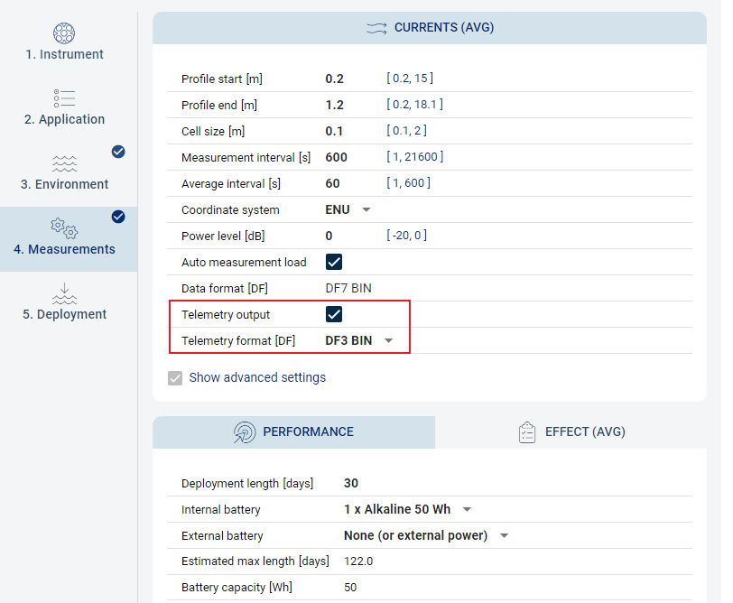
Figure 5: Aquadopp measurement settings.
- Note that the X-Series logger can support a maximum of 160 parameters from the sensor.
- The number of active parameters can be determined using the formula (NC*NB)
- NC represents the number of cells, which is based on the cell size (m) and the overall profile size (difference between profile end and profile start).
- Example:
- Cell size (CS) = 0.1m
- Profile start (PS) = 0.2m
- Profile end (PE) = 1.2m
- NC = (PE – PS)/CS
- Example:
- NB represents the number of measurement beams used, which is dependent on the sensor.
- NC represents the number of cells, which is based on the cell size (m) and the overall profile size (difference between profile end and profile start).
- After calculating, if the number of parameters is greater than 160, adjust the cell size or profile range before continuing.
- The number of active parameters can be determined using the formula (NC*NB)
- Go to the Deployment step and select SAVE TO FILE and SAVE TO INSTRUMENT.
- Follow the next steps below to fully configure and deploy the device.
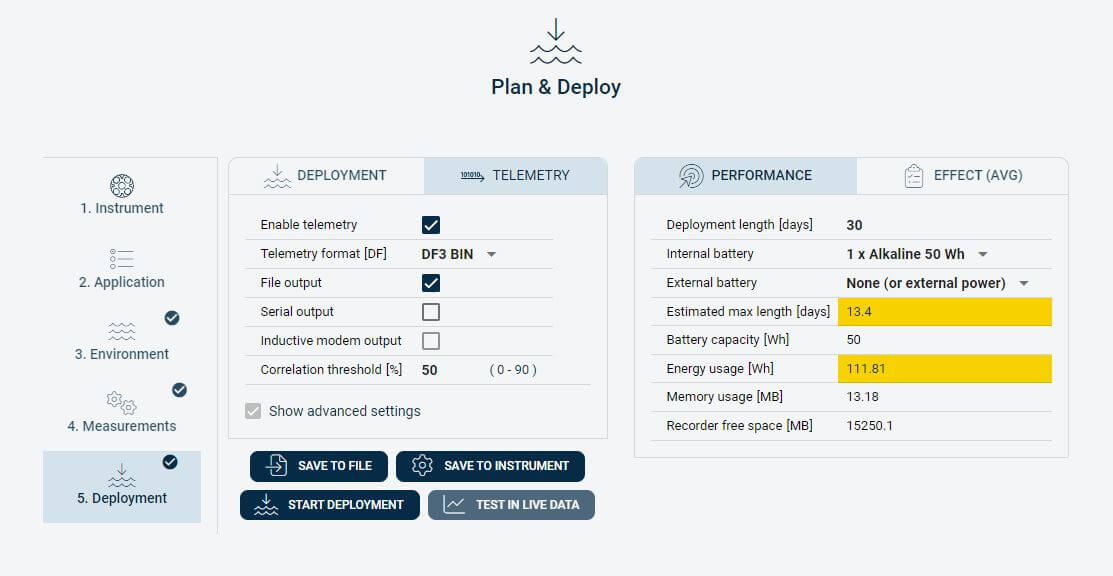
Figure 6: Deployment settings.
Confirm Communication Settings
Certain configuration settings required to interface the Aquadopp with an X-Series logger may not be properly translated through the deployment file. Update the telemetry settings through a terminal (e.g., Tera Term) and make changes where required.
- Set the following communication settings in the Terminal:
- Baud rate: 115200
- Data Bit: 8-bit
- Parity: None
- Stop bit: 1
- Flow Control: None
- Turning on “Local Echo” is recommended to see the commands as they are typed out.
- Once connected to a terminal, send MC to put the device in command mode.
- Change the baud rate to 9600 bps by sending SETINST,BR=9600
- Note: After the baud rate is changed, the baud rate in the terminal must be updated to continue with proper communication.
- Send the gettmavg command and check the instrument response to confirm the telemetry file settings.
- Verify the telemetry settings returned match the values below.
- EN=1, indicates data output is enabled.
- TV=1, indicating velocity values for each deployment cell are enabled.
- TA=0, indicating amplitude values for each deployment cell are turned off.
- TC=0, indicating correlation values for each deployment cell are turned off.
- FO=1, indicates the file output is enabled.
- SO=0, indicates that serial output is disabled.
- DF=3, indicates that binary data output is enabled
- Example output: 1, 1, 1, 360, 1, 0, 0, “ENU”, 1, 0, 3, 0, 0, 0, 50, 0
- Verify the telemetry settings returned match the values below.
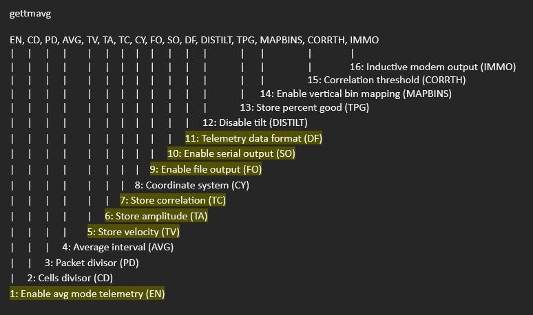
Figure 7: Telemetry output format. Yellow highlights indicate important settings for communication.
- If any portion of the telemetry file configuration requires a change, send the settmavg command followed by the parameter indicator and new status.
- For example, to set TA=0, the command settmavg,TA=0 would be sent.
- Multiple commands can be sent in a single line provided each value is separated by a comma and no space.
Save Configuration Changes and Redeploy
Once the deployment settings are verified to be correct, and the maximum number of parameters is not exceeded, save all settings.
- Send the following commands
- save,all
- format,code=9999
- deploy
- Close out of the terminal and disconnect the instrument from the communication cable.
- Connect the sensor to the logger through the sensor cable and power up the logger to begin sensor detection/data collection.
2. Automatic Sensor Detection
After updating the settings and connecting the Aquadopp to an X-Series data logger, the sensor can be programmed onto the logger via automatic detection.
X-Series Logger Detection and Script Information
X-Series data loggers include a pre-loaded Nortek Aquadopp script. Use the link below to confirm the script is enabled before running a sensor detection.
| Logger Script Number | Sensor Interface | Baud Rate | Power Type | Warmup Period (sec) | Frame |
| 3015 | RS-232 | 9600 | Continuous | 5 | N81 |
Read Sensor Configuration – Confirm Sensor Detection
After ~5-10 minutes, read the sensor configuration to confirm the Aquadopp and other sensors have been detected on the data logger. Thoroughly review the parameter list to ensure all parameters are accounted for and are measured in the desired units. Let the unit gather a few readings to confirm accurate and reasonable parameter data.
3. Setting up WQData LIVE
Once an X-Series data logger has finished a new sensor detection, it will automatically push the sensor configuration to the WQData LIVE web data center. Follow the three articles below to create a WQData LIVE account and a project/site. Then add the data logger to the project using the included claim code.
- Create a WQData LIVE Account
- Create a Project on WQData LIVE
- Add a Data Logger to a Project on WQData LIVE
Applicable Systems
Real-time water current profiling measurements from Nortek ADCPs are useful in coastal and ocean-based environmental monitoring applications.