
X2 Modbus Output
The X2 Modbus Output tool is designed specifically for applications utilizing a Programmable Logic Controller (PLC) with the Modbus communication protocol (RS-232 or RS-485). The connection from the X2 to the PLC will include a NexSens plug cable (UW-FLx) to one of the X2’s sensor ports, along with a variety of other connection options for linkage to the PLC.
Note: The X2 will act as a Modbus Master.
Software & Logger Requirements
- X2 Base Firmware: v2.20.200922 or higher
- X2 Base Radio RTU Firmware: v2.31.200920 or higher
- CONNECT Software: v2.20.5.4 or higher
Wiring
| Cable Connection | Wire Color | Signal |
| NexSens UW6-FLx* | Red | PWR (+12VDC) |
| Black | GND | |
| NexSens UW8-FLx** | Green | RS485A |
| Blue | RS485B | |
| Black | GND (common) |
*Connects to center 6-pin power port on the X2 data logger.
**Connects to P0, P1, or P2 port on the X2 data logger. Modbus shared between all three ports.
Setup X2 Modbus Output
- Connect the X2 logger to a PC and launch the CONNECT software. Test connection by reading the RTC clock of the logger in the CONFIG tab.
- Click Setup | X2 Modbus Output.
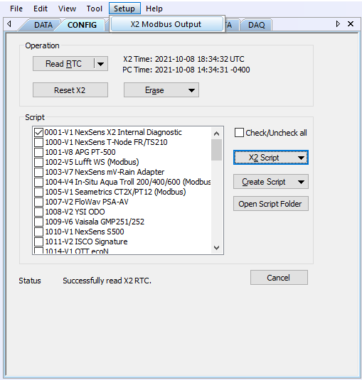
Figure 1: X2 Modbus Output configuration menu.
- Select Read Settings from X2.
- Settings must be read before any changes can be made.
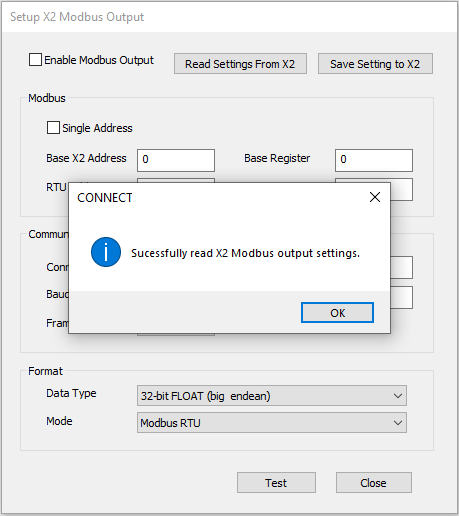
Figure 2: Confirmation that the X2 Modbus output settings have been read.
Modbus Information
- The following Modbus settings can be adjusted on the X2:
- Check Enable Modbus Output at the top of the interface.
- For an X2 radio network, click Single Address to use the same Modbus address for both the X2 base radio and all field radios.
- See the X2 Radio Network section below for more information.
- Insert the Base X2 Address.
- This address corresponds to the Modbus slave (PLC) address that the X2 will use to output data to the PLC.
- Insert the Base Register.
- This register starts from 0 and corresponds to the Modbus slave (PLC) beginning register that the X2 will output to the PLC.
- Parameters from the X2 are written to the Modbus slave (PLC) starting from this register.
- See the X2 Radio Network section below for information on the RTU Address and RTU Register.
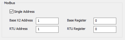
Figure 3: X2 Modbus settings.
Communication Settings
- The following Communication settings can be adjusted on the X2:
- Connection: Choose the Modbus protocol (RS-485 or RS-232) that the X2 will output, which can be recognized by the PLC.
- The X2 sensor port (P0, P1, P2) must be specified for RS-232 since each port contains a separate RS-232 line. Currently, RS-232 is not supported.
- RS-485 communication is shared between each sensor port, thus the port where Modbus output will occur does not need to be specified.
- Baud: The default baud rate is 19200; however, options range from 9600 to 57600.
- Frame:
- E81: 8 data bit, 1 stop bit, even parity
- N81: 8 data bit, 1 stop bit, no parity (default)
- O81: 8 data bit, 1 stop bit, odd parity
- Num Retry: The default is 1 retry; however, the range is from 1 to 254.
- The X2 utilizes a coarse retry. By default, if the X2 does not get a response from the Modbus slave, it conducts 3 retries each separated by 100 milliseconds (msec). Coarse retries are repeated every second.
- Example: If the number of retries is set to 2, the X2 will send data to the slave up to 6 times before ending the retry process.
- Note: Feature not available for the RTU.
- Timeout (msec): This feature represents the timeout (msec) the X2 will wait for the Modbus slave to respond.
- Note: This feature is currently not supported.
- Connection: Choose the Modbus protocol (RS-485 or RS-232) that the X2 will output, which can be recognized by the PLC.
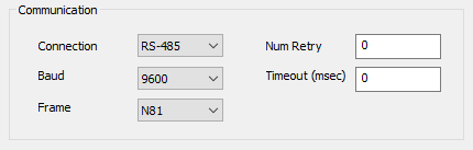
Figure 4: X2 to PLC Communication settings.
Format Settings
- The following Format settings can be adjusted on the X2:
- Data Type: 32-bit FLOAT (big endean) is the only data type currently supported.
- Mode: Modbus RTU is the only mode currently supported.
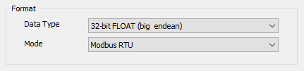
Figure 5: Data Format settings.
Once all changes have been made, click Save Setting to X2.
X2 Radio Network
For a radio network with multiple field radio X2’s, both data from the base radio (directly connected to the PLC) and field radios are set to output in Modbus.
RTU Address and Register
- RTU Address: The Modbus slave (PLC) address offset for each field radio X2.
- See example below in the Single Address Unchecked section.
- RTU Register: The Modbus slave (PLC) beginning register offset to each field radio X2.
- Register will be different whether the Single Address is checked or unchecked.
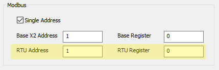
Figure 6: RTU Address and Register under the Modbus settings.
Single Address Checked
The base X2 and all field X2 data are sent to the same Modbus address. The RTU Address is ignored. The RTU Register is an offset from the Base Register described below.
- Example: Base X2 Address = 1; Base Register = 0; RTU Register = 1000
- Base X2 Modbus address = 1
- All field X2 radio Modbus address = 1
- Base X2 begin register = 0
- First field X2 radio begin register = 0 + 1000 = 1000
- Second field X2 radio begin register = 0 + 2000 = 2000
- and so on…
Single Address Unchecked
The base X2 and each field X2 data are sent to a separate Modbus address. The RTU Address for each field X2 radio begins with an offset of 10 from the base radio, with a subsequent increase in the address number for each field radio as described below. All field radio X2 data is sent to the same beginning register (RTU Register).
- Example: Base X2 Address = 1; RTU Address = 10; Base Register = 0; RTU Register = 0
- Base X2 Modbus address = 1
- First field X2 radio Modbus address = 10 + 1 = 11
- Second field X2 radio Modbus address = 10 + 2 = 12
- and so on…
- Base X2 begin register = 0
- Each field X2 radio begin register = 0
Once all changes have been made, click Save Setting to X2.
Register Mapping
- The first parameter is always a 32-bit big Endean UTC epoch time stamp (number of seconds since midnight 1/1/1970). The following web converter can be used to convert to a readable timestamp.
- Epoch Converter – This timestamp is mapped to the first register specified in Base Register or RTU Register.
- Each measured parameter is mapped to the next register. An online converter below can be used to convert from a 32-bit hex representation to a readable floating point number.
- Float Converter
- Example:
- Base Register = 0
- Timestamp = 0x4EBED3CA
- First Parameter = Temperature
- Measured Value = 22.14 C (0x41B11EB8)
- Second Parameter = Depth
- Measured Value = 2.79 m (0x40328F5C)
- Example:
- Float Converter
| Register | Hex Value | Note |
| 0x0000 | 0x4EBE | Most significant 16-bit of timestamp (9/22/2020 11:50:00) |
| 0x0001 | 0xD3CA | Least significant 16-bit of timestamp |
| 0x0002 | 0x41B1 | Most significant 16-bit of temperature (24.14 C) |
| 0x0003 | 0x1EB8 | Least significant 16-bit of temperature |
| 0x0004 | 0x4032 | Most significant 16-bit of depth (2.79 m) |
| 0x0005 | 0x8F5C | Least significant 16-bit of depth |
Example Modbus Output
The following example represents an X2 radio network including one base and one field radio. The base radio is connected to the PLC where data from both units is uploaded. The field radio contains a 19HVS GPS unit and (3) NexSens T-Node FR sensors.
| Example Modbus Ouput | Description | Units | Register Number | Value from Example Output |
| 1 | Base Data Logger Address | — | 1 | |
| 10 | Modbus Function (Holding Register) | — | — | 16 |
| 00 00 | Register number | — | — | 0 |
| 00 1A | # of Registers | — | — | 26 |
| 34 | # of bytes | — | — | 52 |
| 61 AF 5D 28 | Date and Time (UTC) | — | 0 | Tuesday, December 7, 2021 8:10:00 |
| 40 58 93 AF | Processor Power | Volts | 2 | 3.38 |
| 40 3D 3F 4B | RTC Power | Volts | 4 | 2.95 |
| 40 95 E3 27 | Primary Power | Volts | 6 | 4.68 |
| 3D 55 76 28 | Secondary Power | Volts | 8 | 0.052 |
| 41 41 25 30 | Sensor Power | Volts | 10 | 12.07 |
| 43 3A 09 00 | Total System Current | MilliAmps | 12 | 186.03 |
| 3F E1 00 00 | Sensor Current | MilliAmps | 14 | 1.75 |
| 44 79 4E BD | Internal Pressure | mBar | 16 | 997.23 |
| 41 9F D2 04 | Internal Temperature | C | 18 | 19.97 |
| 3E C9 52 43 | Internal Humidity | % | 20 | 0.39 |
| C2 AA 00 00 | Cell Signal Strength | dB | 22 | -85 |
| 00 00 00 00 | Cell Status | — | 24 | 0 |
| 97 C7 | Checksum | — | — | |
| 1 | Field Data Logger Address | — | — | 1 |
| 10 | Modbus Function (Holding Register) | — | — | 16 |
| 03 E8 | Register number | — | — | 1000 |
| 00 26 | # of Modbus Registers | — | — | 38 |
| 4C | # of bytes | — | — | 76 |
| 61 AF 5D 28 | Date and Time (UTC) | — | 1000 | Tuesday, December 7, 2021 8:10:00 |
| 40 56 08 C7 | Processor Power | Volts | 1002 | 3.34 |
| 40 3C F1 50 | RTC Power | Volts | 1004 | 2.95 |
| 41 4C E2 F6 | Primary Power | Volts | 1006 | 12.8 |
| 3D 9D 36 27 | Secondary Power | Volts | 1008 | 0.076 |
| 41 3F DF 3B | Sensor Power | Volts | 1010 | 11.99 |
| 42 D4 80 00 | Total System Current | MilliAmps | 1012 | 106.25 |
| 42 3D 42 00 | Sensor Current | MilliAmps | 1014 | 47.31 |
| C7 C3 82 00 | Internal Pressure | mBar | 1016 | -100100 |
| 41 C4 D5 60 | Internal Temperature | C | 1018 | 24.6 |
| 3F 32 20 00 | Internal Humidity | % | 1020 | 0.69 |
| C2 9A 00 00 | Cell Signal Strength | dB | 1022 | -77 |
| 00 00 00 00 | Cell Status | — | 1024 | 0 |
| 41 AD B0 FD | Temp 00 | C | 1026 | 21.71 |
| 41 AF 0D CD | Temp 01 | C | 1028 | 21.88 |
| 41 AB 6B 5D | Temp 02 | C | 1030 | 21.42 |
| 42 1F 21 60 | Latitude | Deg | 1032 | 39.78 |
| C2 A7 FC DC | Longitude | Deg | 1034 | -83.99 |
| 43 66 CC CD | Altitude | m | 1036 | 230.8 |
| AB 7C | Checksum | — | — | — |
Testing Communication
Communication between the X2 data logger and PLC can be determined using the Test button on the Modbus Output interface. If the data below is received by the PLC, Modbus output communication is confirmed.
- The Test button sends the following data to the PLC:
- 0x01020304