Configure an iSIC-V2 to Post to WQData LIVE
iSIC-V2 data loggers equipped with Ethernet telemetry or an internal cellular modem are designed to push data directly to the WQData LIVE cloud datacenter. For systems integrating analog sensors or generic sensor types (where the default sensor auto-detection process is not feasible), it is necessary to program the data loggers first using the iChart software.
Required Equipment
- iSIC-V2 Data Logger
- Windows PC (iChart and Tera Term installed)
- Serial DB9 Cable
- USB to RS485 cable (flying lead or UW6 termination)
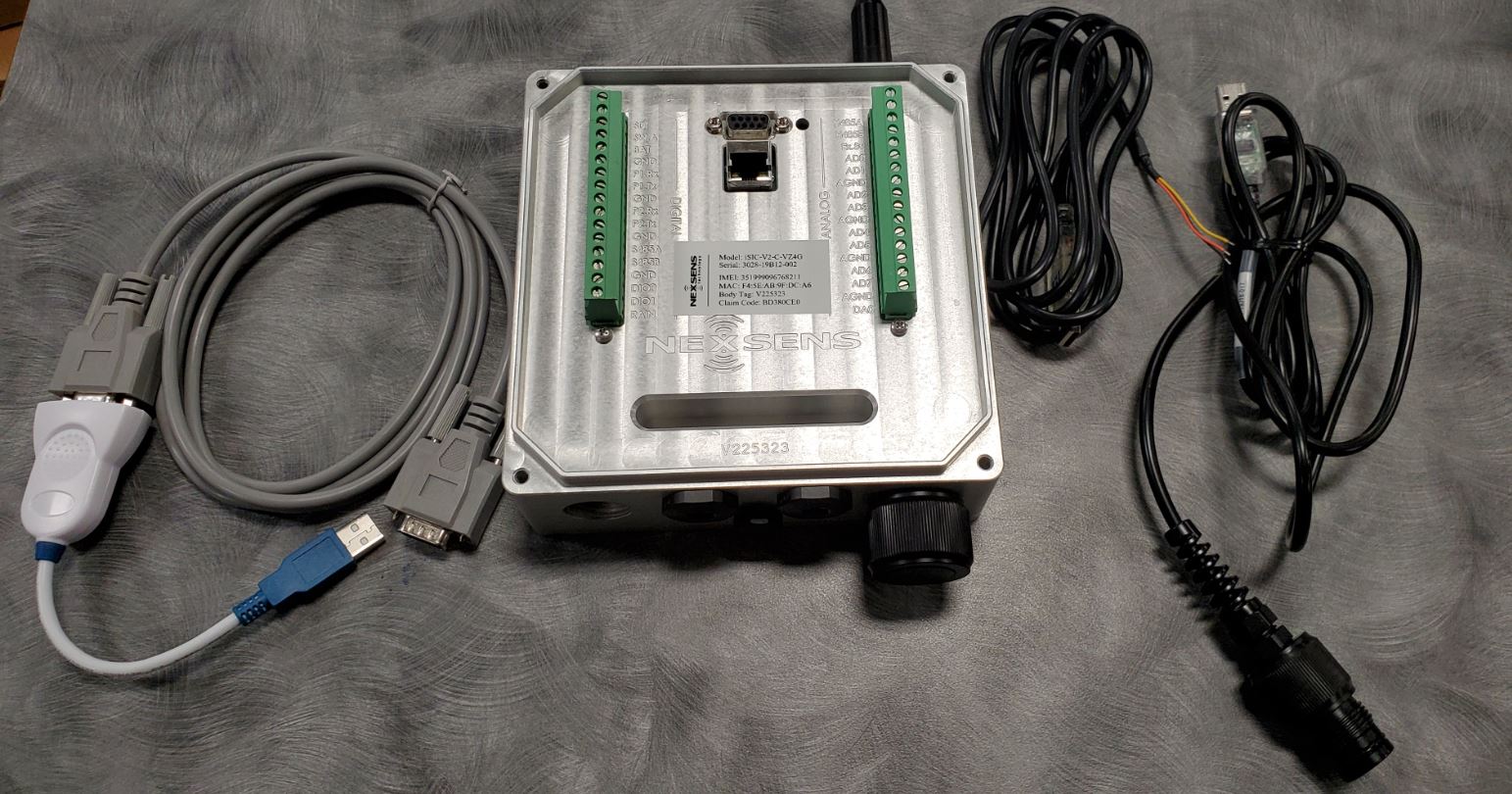
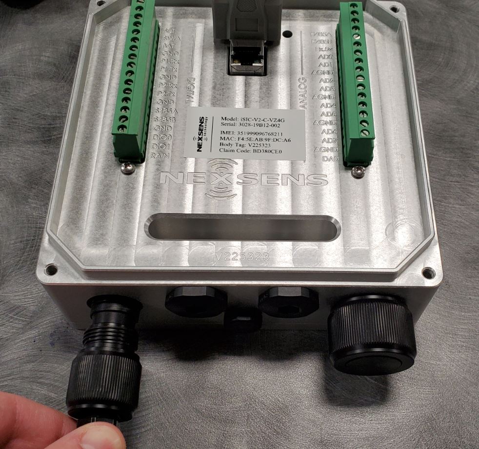
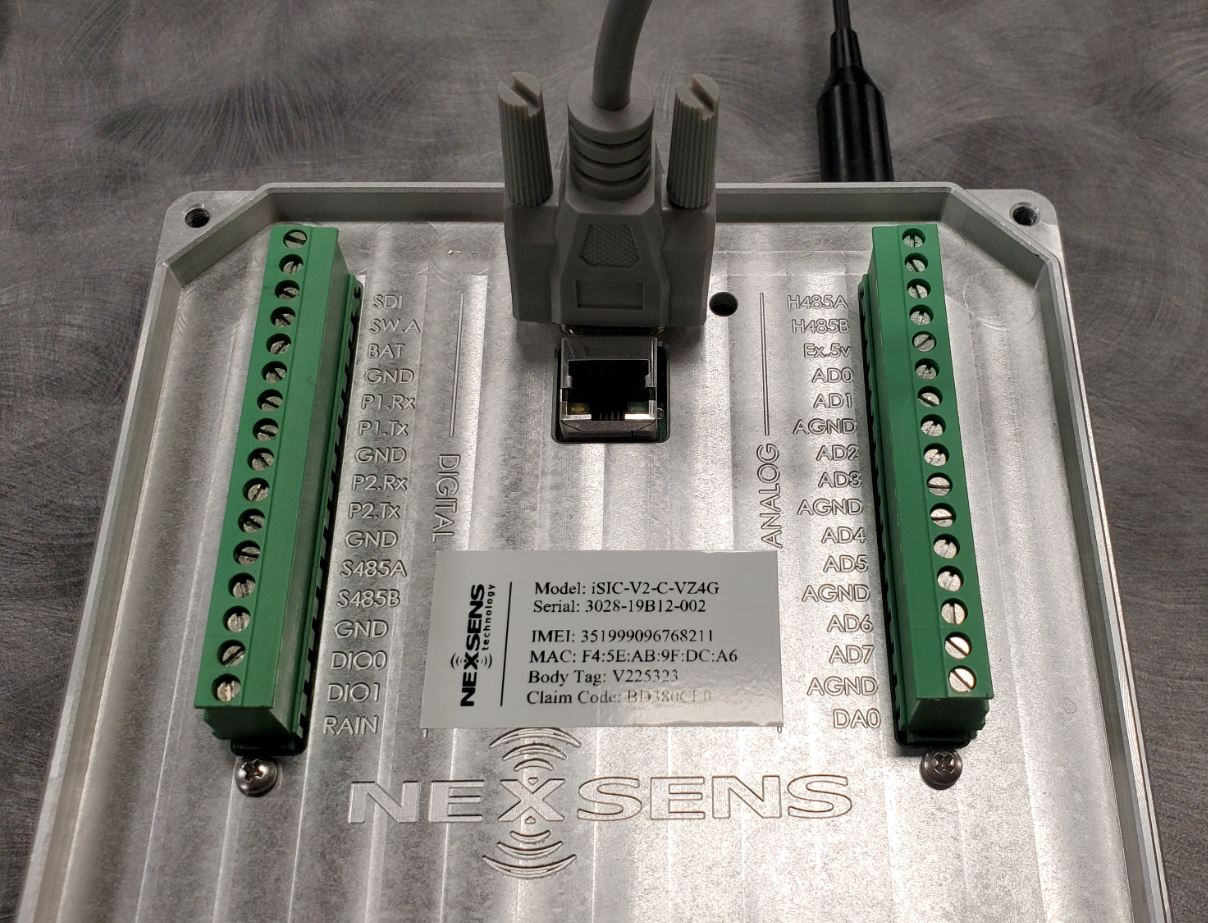
iSIC-V2 logger, Serial (DB9) Cable, and RS485 USB cable (flying lead or UW6 plug version- both shown).
Program using iChart
- Connect a serial cable to the DB9 connector on front of the iSIC-V2.
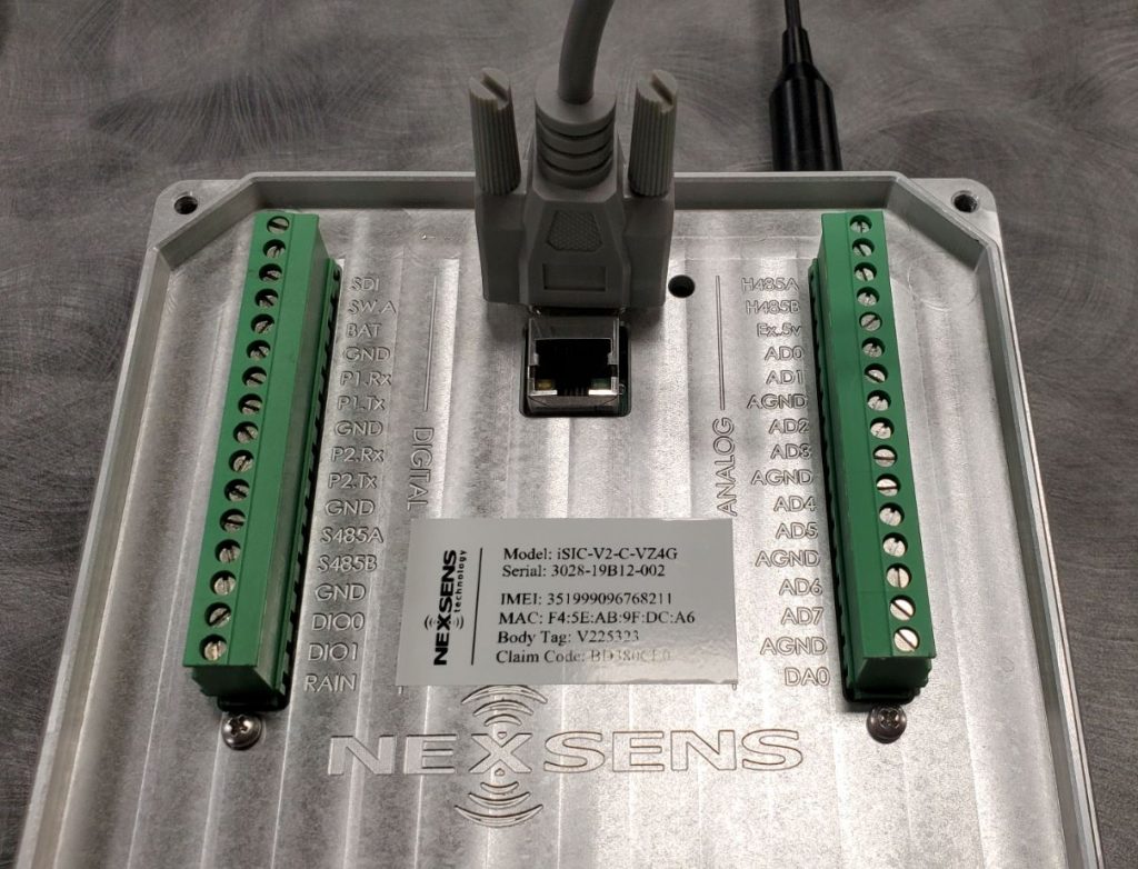
Connect DB9 Serial Cable to iSIC-V2
- Apply external 5-12VDC power through the 6-pin port at the bottom of the logger.
Apply External Power-a buzzer will sound on power-up.
- Launch the iChart software, select the option to ‘Open without Project’.

Select ‘Open Without Project’ option.
- Navigate to File|New Project in the main menu of iChart, provide a name for the new project file, and follow the Setup Device Wizard process.
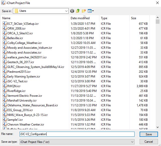
Name new iChart Project file.
- Step 1– Add a generic site to the project.
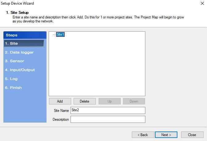
Add a Site to the new iChart project.
- Step 2– Select the iSIC data logger option underneath the NexSens manufacturer field and click Add to put it under the site created in the previous step.
- Do NOT select the ‘iSIC-V2’ logger type from the menu. Only use the standard iSIC option.
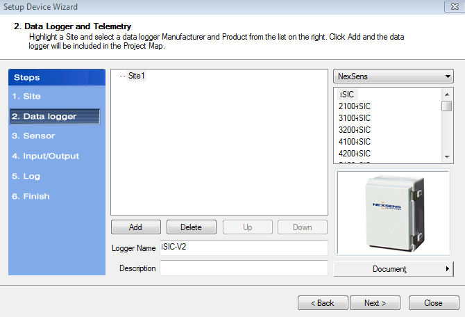
Add an iSIC data logger to the site, naming it if desired.
- On the communication menu that appears, select the COM port associated with the RS232 DB9 serial cable and verify the connection test passes. Then click Close and OK.

Select the appropriate COM port for the USB Cable, then click the ‘Test Connection’ button.
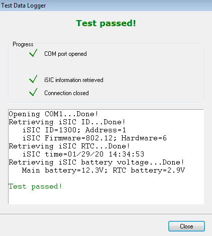

Connection test pass.
- Do NOT select the ‘iSIC-V2’ logger type from the menu. Only use the standard iSIC option.
- Step 3– Choose NexSens from the sensor manufactuer list, select the iSIC Battery sensor, and Add the parameter. This is important for diagnostic purposes.
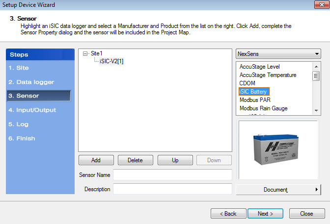

Add the iSIC battery voltage sensor to track system power.
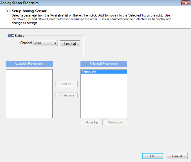

Sensor Properties menu for the iSIC Battery sensor, click OK.
- Continue to add sensors individually, searching by manufacturer name, until all connected sensors have been assigned.
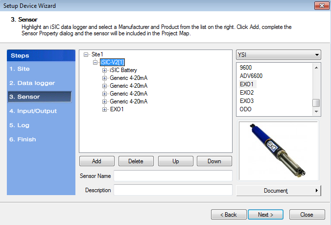

All sensors added to the iSIC-V2.
- Continue to add sensors individually, searching by manufacturer name, until all connected sensors have been assigned.
- Step 4– Add IO Control if required.
- Step 5– Set the sensor sample and log interval desired for the system.


Specify the sensor sample and log frequency.
- Step 6– Left click on the iSIC logger to highlight it and select Program. Acknowledge that you wish to program the system and click the Finish button once the programming completion message appears.


Select the logger and click the ‘Program iSIC’ button.
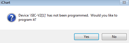

Choose ‘Yes’ when the program prompt appears.


Acknowledge the program completion message and click the ‘Finish’ button in the Setup Device Wizard.
- Step 1– Add a generic site to the project.
- Once the iChart programming is complete all of the added system parameters will appear in a blank data chart.
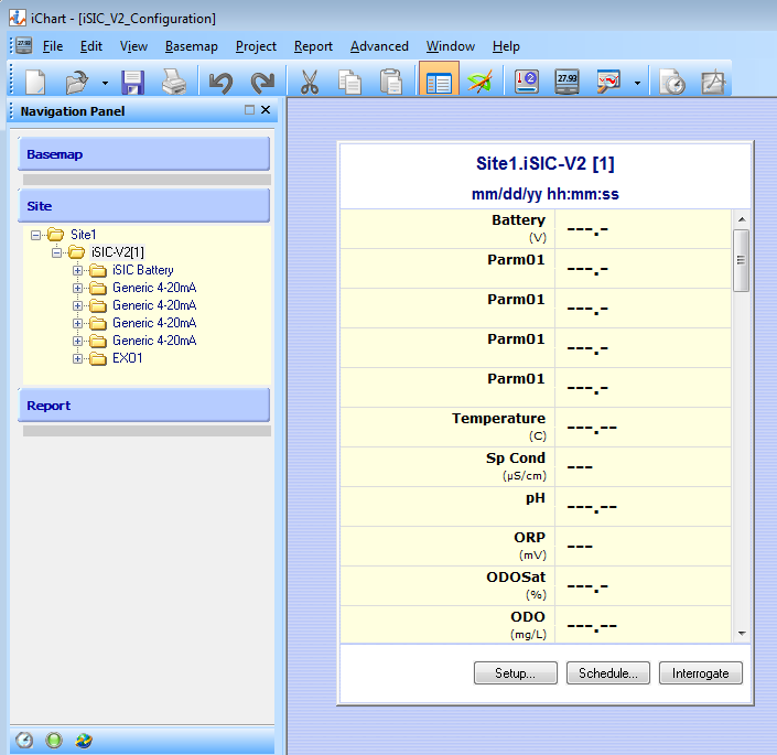

iChart programming completed, view of main project screen.
Complete WQData LIVE Setup
- Establish a connection in Tera Term.
- Send the syncrtc command to set the iSIC-V2 to UTC-Standard time.


Sending the syncrtc command through the terminal.
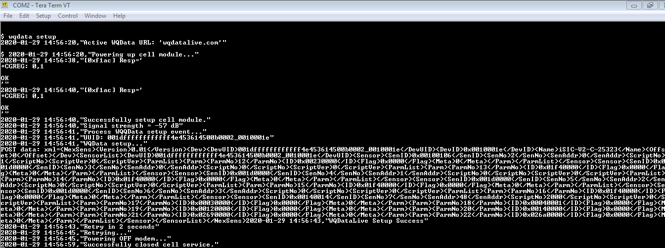
- Send the wqdata setup command to have the iChart-programmed logger configuration synced to WQData LIVE.


Send the ‘wqdata setup’ command to sync the iChart programming of the system with WQData LIVE.
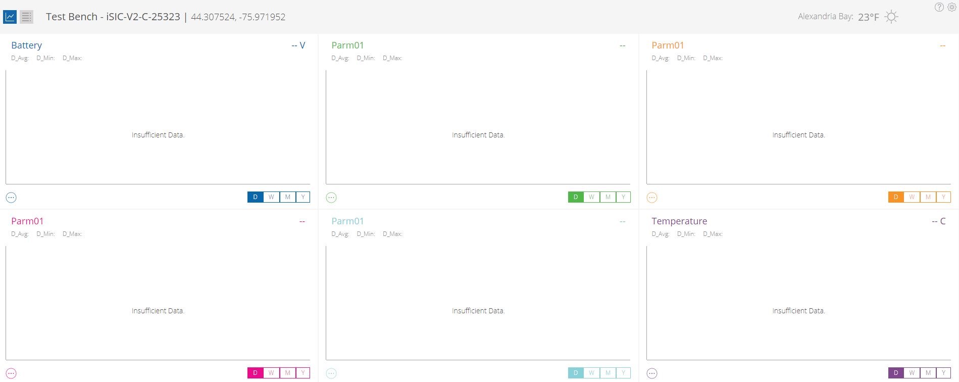
- Verify that all sensor parameters are now listed for the logger on WQData LIVE. Note that the fields will be blank until the first logged readings have been transmitted to the site.


Logger configuration pushed successfully.
- The default iSIC-V2 transmission frequency is 1 hour. To confirm the system is reporting data properly it may be desirable to adjust this interval temporarily during testing:
- Option 1- Set the transmission interval through WQData LIVE remotely and cycle power on the iSIC-V2 to apply the change immediately.
- Option 2- Send the terminal command set txintv xxx , where ‘xxx’ is the number of seconds for the transmission frequency.
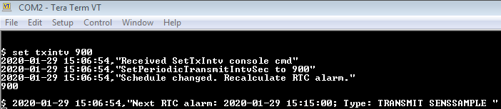

Setting the iSIC-V2 transmission interval to 15 minutes using the terminal.