
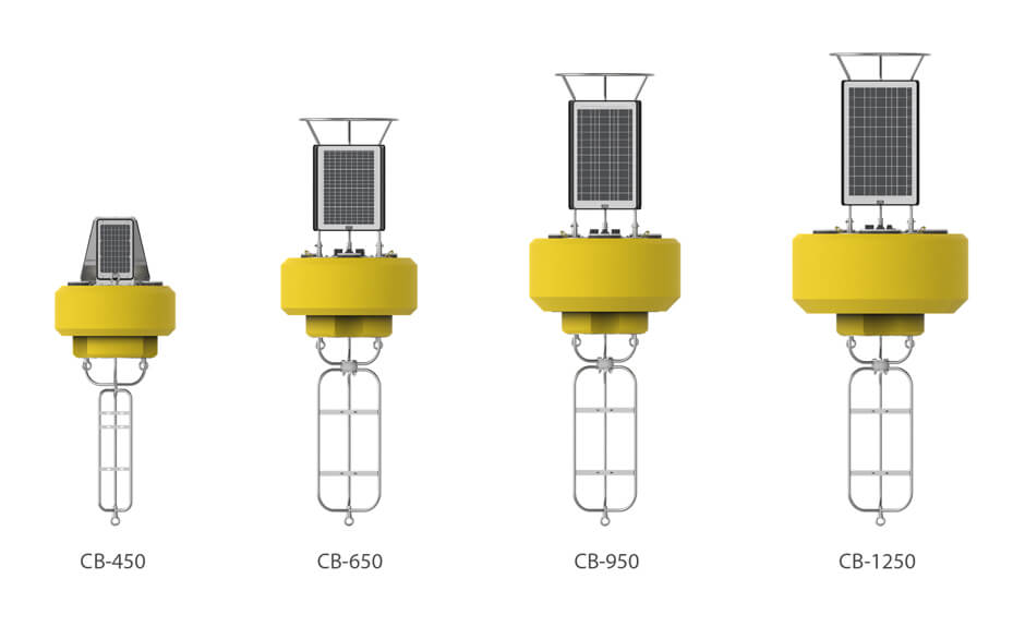
Customizing CB-Series Buoys
While NexSens provides turnkey systems, the CB-Series data buoys are easily customized with user-preferred power supplies, electronics, sensors, accessories and mounting hardware.
Buoy Platforms
This document covers the CB-450, 650, 950 and 1250 customization. For XB-200 applications, see Customizing the XB-200.
When selecting a buoy platform, careful consideration of anticipated sea state, battery and solar capacity, and workboat logistics for size and weight is important (see buoy comparison)
Consider Buoyancy, Freeboard and Stability
Net buoyancy specifications are for the assembled hull, cage and solar tower only. Ballast, sensors, data loggers, instruments, batteries, and navigation aids are considered payload and not included in the net buoyancy specification.
Select a buoy platform with adequate net buoyancy and freeboard to support the planned payload and adequate ballast to provide the desired stability.
Freeboard should be sufficient to prevent frequent swamping or splashing over the top of the buoy hull. A general rule of thumb is that at least two-thirds of the buoy hull and not less than half should be above the water surface.
Stability should be optimized by adding ballast to offset wave, wind and topside weight. Generally, it’s best to keep the center-of-gravity within a few inches of the bottom of the hull (see below).

If excess mooring weight results in insufficient freeboard, auxiliary floatation (either surface, subsurface, or a combination of both) should be used.
Sea State
Waves’ height, period and direction are influenced by wind and swell. Select a buoy platform and mooring design for the worst-case sea state. The larger platform buoys are typically required for stronger sea states.
Solar Charging and Battery Power
Solar and battery options should be based on a power budget that includes all electrical equipment, sensors and telemetry duty cycle demand.
The tower has three solar panels placed around the buoy. This design ensures that at least one panel gets sunlight as the buoy turns in the water. Reverse polarity protection ensures shaded panels do not draw power from the system. Shaded panels should be excluded from the power budget.
| CB-450 | CB-650 | CB-950 | CB-1250 | |
| Power | (3) 15-watt | (3) 32-watt | (3) 46-watt | (3) 71-watt |
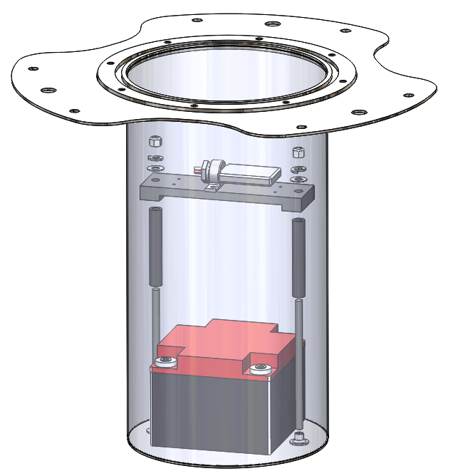
There are four battery assembly options (CB-A05-X), which include a solar regulator, one or more parallel wired batteries, mounting brackets, tie-down rods and a cable with a UW6 connector.
Warning! The battery well is constructed of stainless steel and is conductive. Use caution when installing or replacing any batteries and using metals tools. Shorting a battery to the metal well can damage the equipment and batteries.
| CB-A05-1 |
CB-A05-2 |
CB-A05-3 | CB-A05-4 | |
| Voltage (V) | (3) 15-watt | (3) 32-watt | (3) 46-watt | (3) 71-watt |
| Capacity (A-hr) | 12 | 12 | 12 | 12 |
| Weight (lbs/kg) | 28 | 56 | 84 | 112 |
| CB-450 | x | x | ||
| CB-650 | x | x | x | |
| CB-950 | x | x | x | |
| CB-1250 | x | x | x | x |
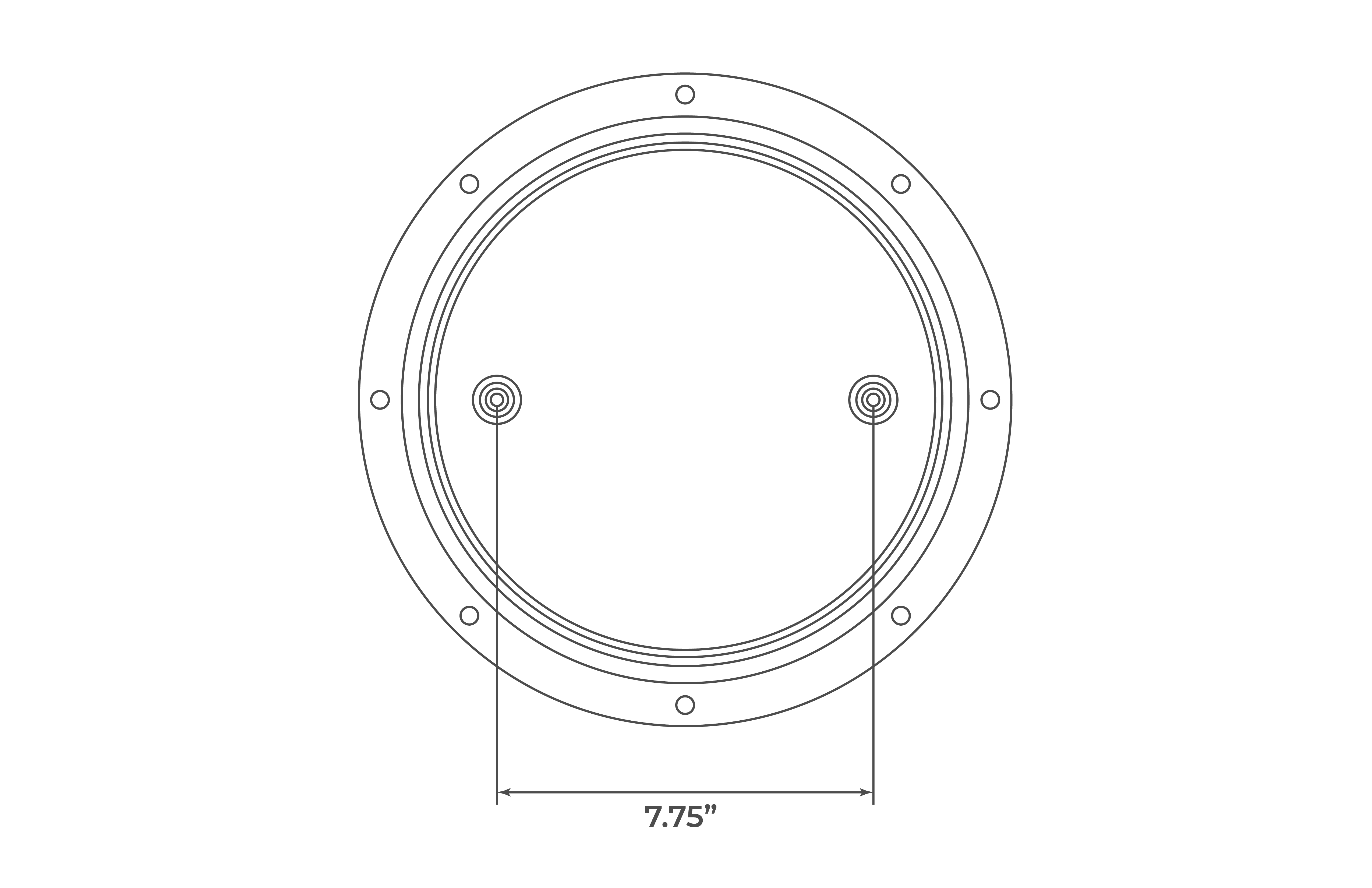
For tie-down of user-supplied battery packs, there are two 3/8″-16 female threaded hubs in the bottom of the battery well.
Optional parts include:
| Part Number | Description |
| N11149 | Threaded rod 3/8-16 x 5ft, 18-8 stainless steel |
| CB0468 | Battery bracket |
| A05 | Battery, 12 VDC, 28 A-Hr |
Humidity Control
Minimizing the internal volume in the battery well limits the amount of moist air that can be trapped when the lid is sealed. Various shapes of closed-cell foam are available as filler.
Optional parts include:
| CB0161 | Wedge and square shape battery filler |
| CB0162 | Round with small center hole |
| CB0163 | Round with large center hole |
Buoy Drawings and Battery Well Dimensions
| Model | Drawing | Height | Inside Diameter |
| CB-450 | 19.5″ (49.5 cm) | 10.3” (26.2 cm) | |
| CB-650 | 21.5″ (54.6 cm) | 10.3” (26.2 cm) | |
| CB-950 | 25.5″ (64.8 cm) | 10.3” (26.2 cm) | |
| CB-1250 | 27.5″ (69.9 cm) | 10.3” (26.2 cm) |
Submersible Sensor Mounting
See the drawings for sensor and equipment mounting.
Three pass-through ports in the foam hull accommodate submersible cable routing and near-surface sensor access in deployment pipes. Water column sensors will need to be mounted to mooring and taut sensor lines with clamps and instrument cages.
| Model | Pass-Through Diameter | Deployment Pipe |
| CB-450 | 4.0″ (10.2 cm) | 914M |
| CB-650 | 4.0″ (10.2 cm) | 914M |
| CB-950 | 6.0″ (15.2 cm) | 916M |
| CB-1250 | 8.0″ (20.3 cm) | 918M |
Battery Well Lid Options
There are four battery well lid options.
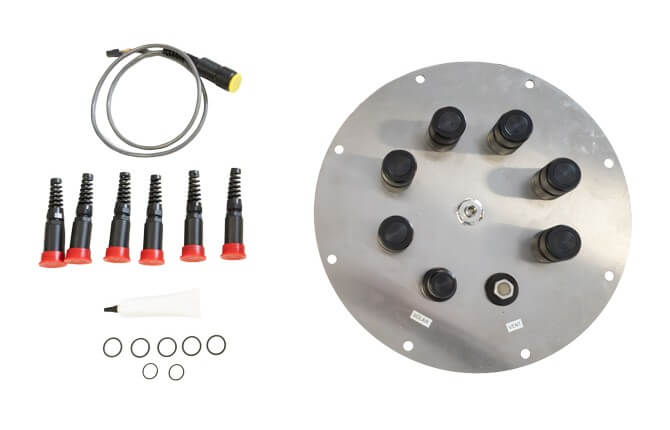
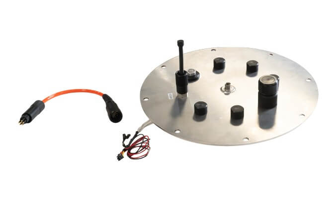
1. CB-PTL Pass Through Lid offers a quick and easy option for wire penetration into the battery well. It supports cable diameters from 0.16″ – 0.31″ (4 to 8 mm) and includes a prewired connector for solar power input. Gland fittings are included for 6 cables. Important: A permanent waterproof seal is made by backfilling with epoxy.
A topside center weld nut is included for mounting the SVS-603HR-UW wave sensor, and 12 bottomside weld nuts accommodate internal electronic mounting.
- Includes:
- (1) Stainless steel lid
- (1) 6-pin power bulkhead with molex connector and power/ground wires
- (1) SA1352 Battery harness cable adapter, Molex 4-pin to UW 6-pin receptacle
- (1) 5 psi UW-PRV Pressure Relief Valve
- (6) UW bulkheads with blank retainers
- (6) PG-9 flex fittings with UW pass-through retainers
- (1) Packet of Molykote 111 compound O-ring grease
- (5) Spare UW retainers and port O-rings
- (2) Spare power port O-rings
- Useful accessories (not included):
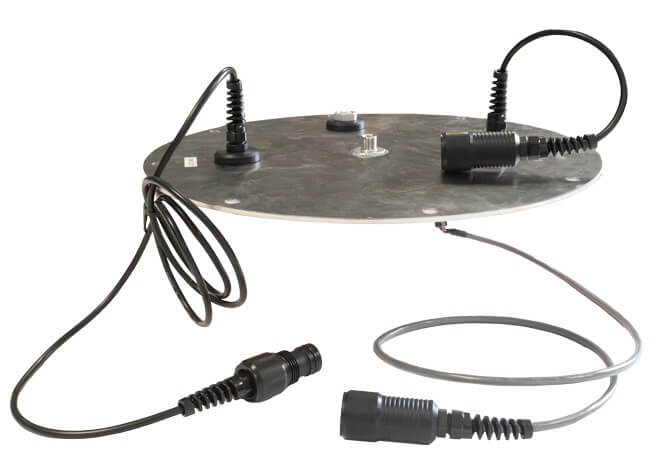
 2. CB-MCL wet-mate Marine Connector Lid is designed for extreme environments with ports for marine-grade MCBH connectors. Includes a bulkhead connector for solar power input.
A topside center weld nut is included for mounting the SVS-603HR-UW wave sensor, and 12 bottomside weld nuts accommodate internal electronic mounting.
- Includes:
- (1) Stainless steel lid
- (1) 6-pin power bulkhead with molex connector and power/ground wires
- (1) SA1352 Battery harness cable adapter, Molex 4-pin to UW 6-pin receptacle
- (1) 5 psi UW-PRV Pressure Relief Valve
- (1) Bushing connector
- Useful Accessories (not included):
- MCBH Male Bulkhead Connectors (4-pin, 5-pin, 6-pin or 8-pin, use with MCDC Female Dummy Plugs and locking sleeve)
- RF-BULK RF Bulkhead Connector Assembly can be used instead of the bushing connector.
- MCBH Female Bulkhead Connectors (4-pin, 5-pin, 6-pin or 8-pin, use with MCDC Male Dummy Plugs) can be used instead of the MCBH Male Bulkhead Connectors.
 3. X3L NexSens CB-Series Data Buoy X3 Lid with minimal battery well penetrations for solar in and power out. Data logging and electronics should be mounted topside.
- Includes:
- (1) Stainless steel lid
- (1) 5 psi UW-PRV Pressure Relief Valve
- (1) Power out cable with 6 pin UW male connector
- (1) solar in cable with 6 pin UX female connector
- (1) (1) SA1352 Battery harness cable adapter, Molex 4-pin to UW 6-pin receptacle
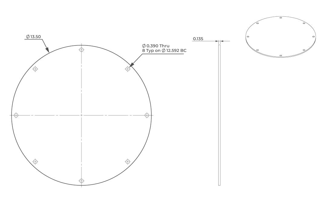
4. Custom plate fabricated with (8) clearance holes for ⅜ bolts on a 12.592-inch bolt circle and drilled penetration holes to accommodate the custom application.
Buoy Accessories
Commonly used accessories are listed below.
| Part | Compatible Systems |
| M550-F-Y | For nighttime visibility on the CB-450 without an X3 logger. |
| M550-P-Y | For nighttime visibility on the CB-450 with an X3 logger. |
| M650H-Y | For nighttime visibility on CB-650, CB-950 and CB-1250 buoys. |
| CB-RR | For visibility on ship radar screens, mounts to CB-650, CB-950 and CB-1250 buoys. |
| CB-CCA | For strengthening connection of instrument cage on CB-450 buoys (included with CB-650 and larger). |
| CB-ZA | For protection of stainless steel frame when used in saltwater, recommended two per buoy, requires periodic replacement. |
| CB-PW-AC-60W | For charging CB-A05-X battery pack without opening the buoy battery well. |
| BALxx | For adding counter-ballast to buoys. |
| 91xM | For secure, near-surface instrument deployment with topside access for maintenance. |