
Check Resistance on a UW-FWP
If a sensor wired to a UW-FWP does not communicate with a data logger or begins to display intermittent readings, it is recommended to ohm out the pins on the connector. As communication between water quality sensors and data loggers requires low resistance for proper transmission, ensuring the UW-FWP resistance is within NexSens specifications will eliminate one potential issue.
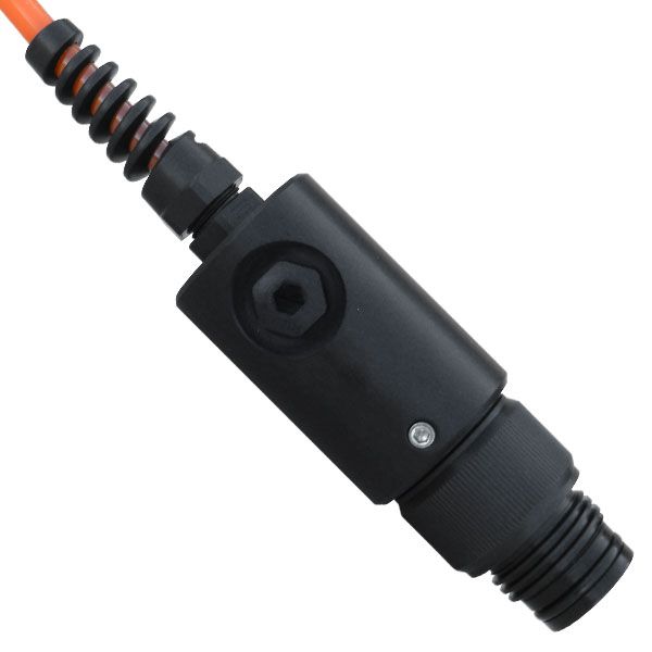
Figure 1: NexSens UW-FWP Field Wireable Plug.
Ohm out UW-FWP with a Multimeter
- Ensure the red lead, or positive input terminal, is connected to the port that contains the Ω symbol, and the black lead, or negative input terminal, is connected to COM. Adjust the dial above the leads to the Ω symbol.
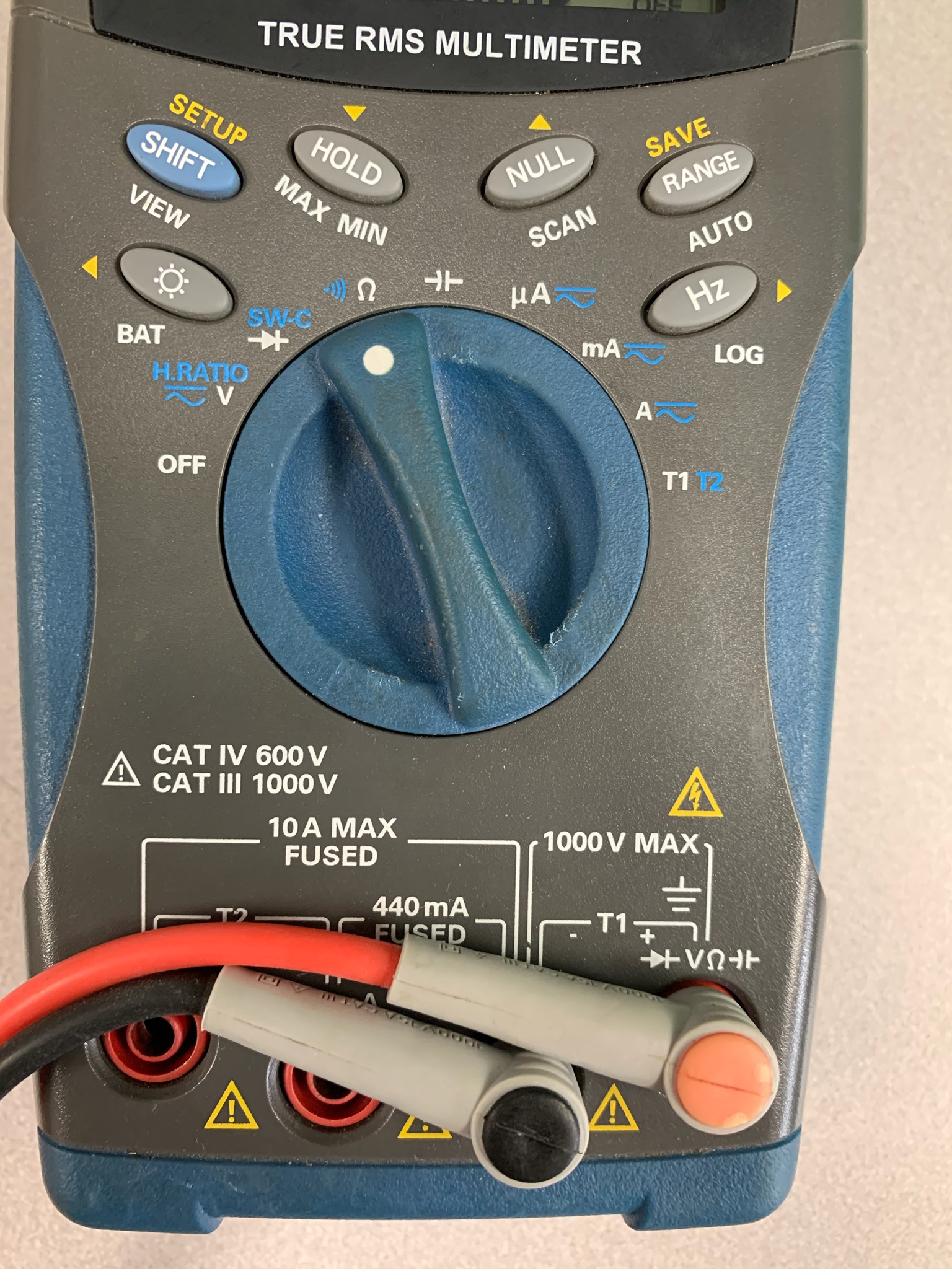
Figure 2: Multimeter connections required to ohm out the UW-FWP pins.
- Touch the two leads together to establish a baseline ohm reading. This reading will be used to account for background resistance.

Figure 3: Touch the multimeter leads together to establish the baseline resistance between the leads.
- Following the wiring diagram below, place one of the leads on a UW-8 Pin, and the other lead on the corresponding J-pin of the UW-FWP.
| SensorBUS Signal | UW-8P Pin | UW-FWP Terminal Name | UW-FWP Terminal Pin |
| RS-232 Tx | 1 | RS232 TX | J1 |
| Ground | 2 | GND | J2 |
| RS-232 Rx | 3 | RS232 RX | J3 |
| 5V | 4 | 5V | J4 |
| 12V | 5 | 12V | J5 |
| SDI-12 | 6 | SDI-12 | J6 |
| RS-485 B | 7 | RS485 B | J7 |
| RS-485 A | 8 | RS485 A | J8 |
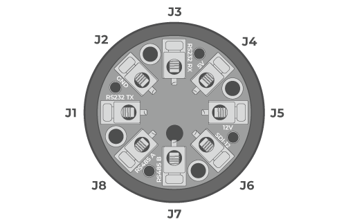
Figure 4: NexSens UW-FWP J-pin out. |
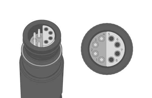
Figure 5: NexSens UW8/UW-FWP Plug pin out. |
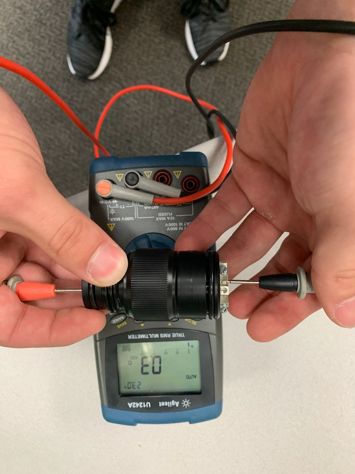
Figure 6: Ohm out the UW-FWP by placing a lead on each connected J-pin and UW-8 pin.
- Subtract the baseline resistance from the resistance measured on the UW-FWP.
- In the example, the final resistance will be 0.3Ω – 0.2Ω = 0.1Ω
For all pin connections, the resistance should be equal to or less than 1 Ω.