
Nortek Aquadopp Current Profiler X2 Integration Guide
The following article provides information on the proper settings required for communication between a Nortek Aquadopp Current Profiler and an X2 data logger. Advanced information describes how the X2 detects and records data from the sensor and includes troubleshooting procedures for common error codes.
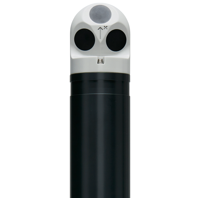
Figure 1: Nortek Aquadopp Current Profiler 1MHz
Nortek Integration
1. Nortek Aquadopp Current Profiler Configuration Requirements
Enable the following settings on the Aquadopp before connecting to the X2:
- Communication
- Protocol: RS-232
- Baud: 9600
- 8 data bit
- 1 stop bit
- No parity
- Power
- The X2 controls power to the Aquadopp, which will begin sampling and outputting data when this power is applied. This method, as an alternative to installing internal batteries, allows the Aquadopp clock and X2 clock to be out of sync and still able to capture data reliably. Thus we recommend the Aquadopp be deployed without internal batteries.
- Number of Cells
- Due to the X2 buffer size limit of 512 bytes, the maximum number of cells the script can support is 52.
- Average Interval
- Typical average intervals are 30, 60, 120, and 300 seconds. For accurate measurements, this interval must be set to less than the log interval.
- Log Interval
- If deployed with internal batteries, the log interval must be set to the X2 log interval for proper data capture. As noted above, the log interval must be greater than the average interval.
- Data Output Format
- The Aquadopp data output must be set to binary format.
- Measurement Mode
- The Aquadopp must be in measurement mode before disconnecting from the PC. Measurement mode can be enabled by sending ST in the terminal emulator command line before exiting the software. The terminal will output ¶¶.
- If gathering data using the internal recorder, select On-line | Start With Recorder.
- Close and select No when asked if you would like to stop data collection.
- Disable Internal Diagnostics
- Internal diagnostics must be disabled within the Aquadopp as this internal measurement interrupts communication between the Aquadopp and X2. The X2 is expecting a certain size of data transferred, based on the parameters read during the sensor detection. Measurements from the internal diagnostics will increase the size of this data transfer and cause a mismatch with the expectations of the X2 data logger.
- See error code: -100008.0
- Internal diagnostics must be disabled within the Aquadopp as this internal measurement interrupts communication between the Aquadopp and X2. The X2 is expecting a certain size of data transferred, based on the parameters read during the sensor detection. Measurements from the internal diagnostics will increase the size of this data transfer and cause a mismatch with the expectations of the X2 data logger.
2. Automatic Sensor Detection
The X-Series data logger includes a pre-loaded Nortek Aquadopp Current Profiler script. Use the CONNECT software to enable the script for sensor detection.
| X2 Script Number | Communication Protocol | Baud Rate | Power Type | Warmup Period (sec) | Frame |
| 3001 | RS-232 | 9600 | Continuous | 5 | N81 |
Note: Ports P1 and P2 on the X2 data logger share a universal asynchronous receiver-transmitter (UART). Thus, if one sensor communicating via RS-232 finishes its reading while connected to one of these ports, it will close the RS-232 channel on both ports. Considering the long warmup/measurement time for the Aquadopp (~65 seconds) and its lower 3000-level script number (3001), connecting the Aquadopp into these ports with another RS-232 sensor (using scripts higher than 3001) may interrupt the Aquadopp readings. It is always recommended to detect the Nortek Aquadopp in port P0 when using a second RS-232 sensor.
Once the script is enabled, run the automatic sensor detection:
Nortek Aquadopp Current Profiler Parameter List
| Parameter | Unit | Description |
| Error Code | — | — |
| Battery | Voltage (V) | |
| Sound Speed | Meters per second (m/s) | — |
| Heading | Degrees (deg) | — |
| Pitch | Degrees (deg) | — |
| Roll | Degrees (deg) | — |
| Pressure | Decibar (dbar) | Surrounding water pressure |
| Status | — | |
| Temperature | Celsius (C) | — |
| Vel.x | Millimeters per second (mm/s) | Velocity for beam 1 (X or East) |
| Vel.y | Millimeters per second (mm/s) | Velocity for beam 2 (Y or North) |
| Vel.z | Millimeters per second (mm/s) | Velocity for beam 3 (Z or Up) |
| Amplitude 1 | Counts | Signal strength for beam 1 |
| Amplitude 2 | Counts | Signal strength for beam 2 |
| Amplitude 3 | Counts | Signal strength for beam 3 |
Advanced Information
Example of X2 Sensor Detection
- Turn power ON
- Wait for 5 to 30 seconds warmup
- Send break.
- If the Aquadopp responds with either “AQUAPRO” or “AQUADOPP” to the break, the script has found a connected Aquadopp.
- If the Aquadopp responds with “Confirm:”, send “MC” command to switch to command mode then look for “AQUAPRO” or “AQUADOPP” from the response to the MC command.
- Send “GC” command to get the configuration.
- Parse GC respond for “number of cells” and “average interval”.
- Save the number of cell and average interval to the X2 SDCard cfg file.
- Send “ST” command to put the Aquadopp into measurement mode
Example of X2 Sensor Reading
- Turn power ON
- Wait for 5 seconds warmup
- Read the ‘number of cell’ and ‘average interval’ from the cfg file on the SDCard.
- Wait for average interval plus 5 seconds.
- Compute the buffer size to hold Aquadopp data: 32 + 9*numcell.
- Wait for data with 1 second timeout.
- Parse and save data to the SDCard
- If no respond, store data as -100000
Error Code:
- -100000: timeout. Possible causes are:
- Bad wiring
- Wrong baud rate
- Wrong communication frame rate
- Average interval has changed since the last sensor detection
- Insufficient power (i.e. power from 5V USB as opposed to 12V battery)
- Bad checksum. This typically results from poor communication.
- Fail to read the number of cells or average interval from the SD card. This is typically caused by corrupted SD card, SD card was replaced, or sensor configuration file was removed from the SD card.
- -100008: mismatch buffer size. Binary data from the Aquadopp is not the same as the buffer size computed by the script. Possible causes are:
- The number of cells has changed since the last sensor detection.
- Poor wiring causing some data to be dropped.
Nortek Aquadopp Wiring Information
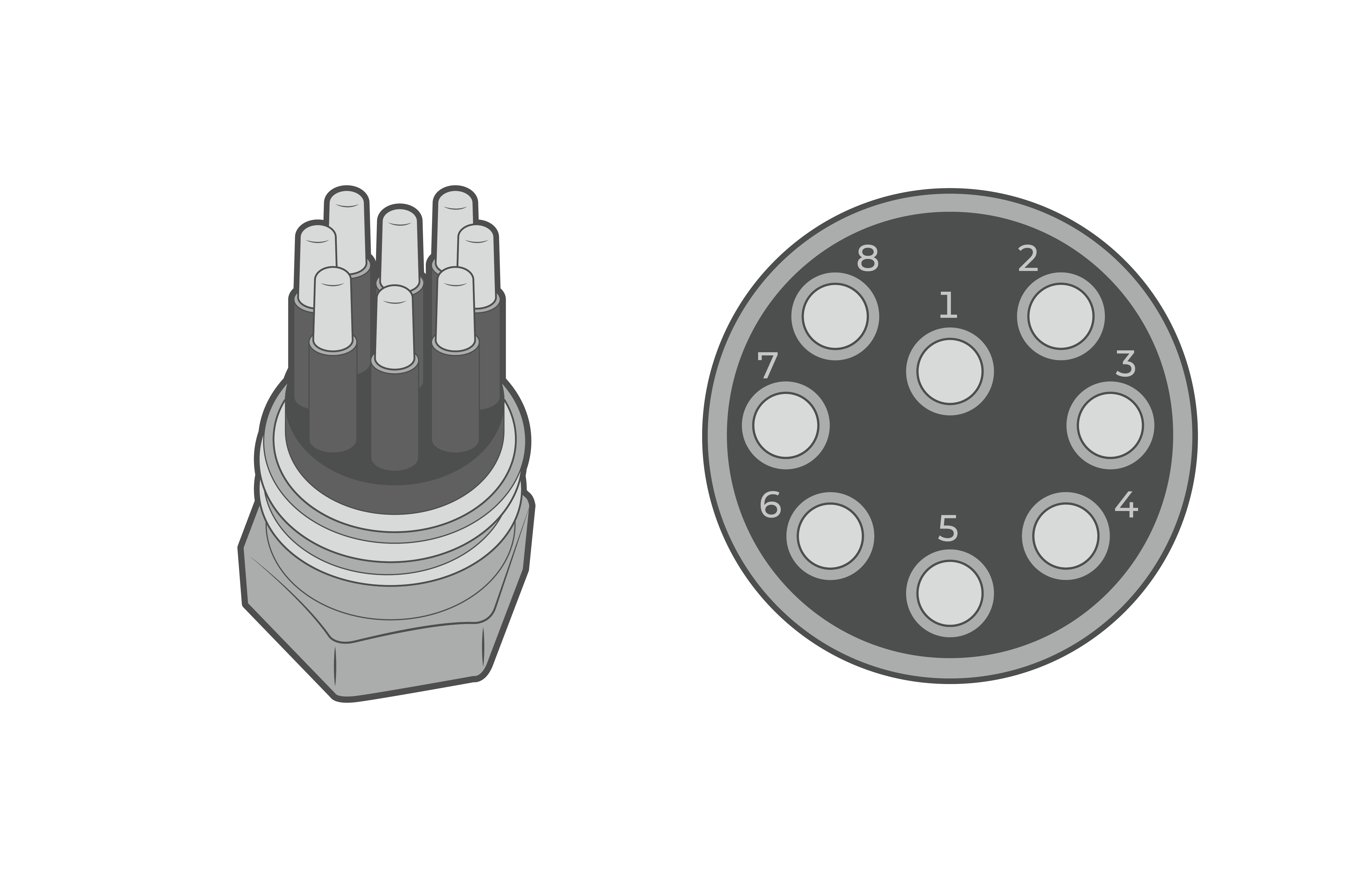
Figure 2: MCIL-8-MP sensor port on X2-CBMC/ MCIL-8 cable (male view) |
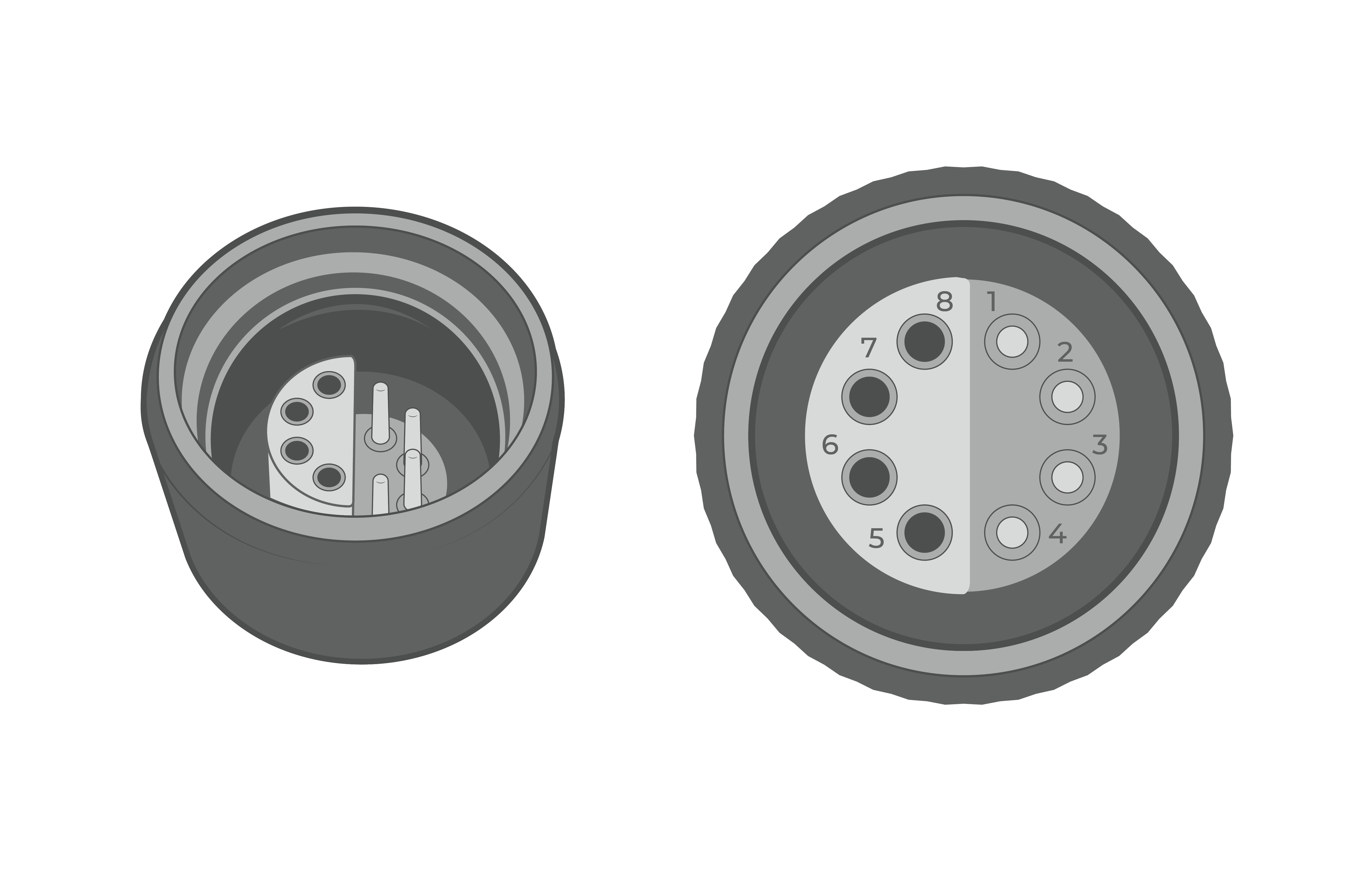
Figure 3: X2 UW Sensor Port. |
| Nortek AWAC MCIL-8 Sensor Pin | Nortek Signal | NexSens MCIL-8-MP Wire Color* | NexSens MCIL-8/UW Plug Pin | X2 Signal | X2/X2-CBMC Sensor Port Pin |
| 1 | Power GND | Orange | 2 | GND | 7 |
| 2 | Power + | Black | 5 | 12V | 4 |
| 3 | RS 232 Tx | Red | 3 | RS 232 Rx | 6 |
| 4 | RS 232 Rx | Brown | 1 | RS 232 Tx | 8 |
| 5 | RS 232 GND | Yellow | 2 | GND | 7 |
| 6 | Power Output | White | — | — | — |
| 7 | Analogue ch 2 | Blue | — | — | — |
| 8 | Analogue ch 1 | Green | — | — | — |
| Screen | GND | Bare | 2 | GND | 7 |
*Wire colors only apply to NexSens MCIL/UW plug cables