
If an SDI-12 sensor reading shows -99999.99 or -100000 in iChart, it indicates that there is a communication problem between the data logger and the SDI-12 sensor. In this situation, there are several possibilities:
1. Insufficient power supply
2. Loose wiring between the logger and sensor
3. The data logger SDI-12 interface is not functioning correctly
4. The sensor is not functioning correctly or is not programmed for SDI-12 output
5. The sensor does not have the correct SDI-12 address
Power Supply
The power supply must be sufficient for both the NexSens iSIC or SDL500 data logger and the SDI-12 sensor that is connected. The operating range of the iSIC/SDL500 is 5-16 VDC. The operating range for SDI-12 sensors varies by device. Check the manufacturer’s manual to confirm.
Use a voltmeter to check the power supply on the data logger. For iSIC data loggers, the voltage on the internal battery can be measured directly. It is also useful to measure the voltage on the pins where the sensor is connected. In most cases, this will be pins 3 (BAT) and 4 (GND) on the iSIC Digital terminal strip. Sensors may also be connected through the switch power port on pin 2 (SW.A). If connected on switch power, the data logger must be configured to apply power to the sensor for it to take a reading. Click here for more information on configuring switch power.
For SDL500 data loggers, the battery voltage must be measured on the pins of the UW ports. Click here for instructions. Note that ports P1 and T on the bottom bulkhead have switch power capability, so sensors connected to these ports must be configured appropriately.
Wiring
Verify all cable connections and wiring according to the manufacturer’s manual or the Sensor Interface manuals located in the NexSens Knowledge Base.
Make sure all connections are secure and wires are not crimped on the insulation.
SDI-12 Function Test
After verifying the power supply and wired connections, the SDI-12 functions of the sensor and data logger can be tested in iChart:
1. First remove all SDI-12 devices from the iSIC or SDL500 data logger except for the SDI-12 sensor that will be checked. This is to avoid accidentally changing settings on the wrong SDI-12 sensor or possibly changing a sensor to an SDI-12 address that is already being used by another sensor.
2. In iChart, navigate to Advanced | iSIC | iSIC. The iSIC Setup menu will open:
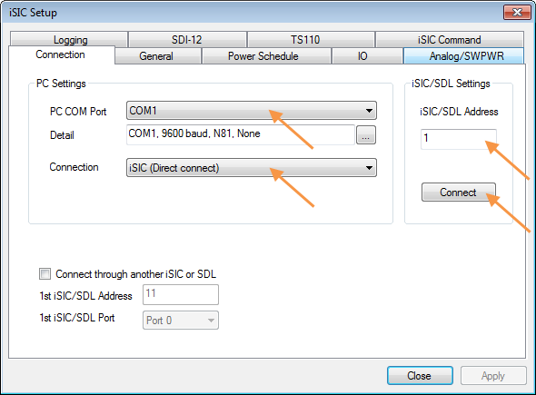
Figure 1: iSIC Setup Menu
3. Enter the appropriate communication settings for the data logger (e.g. COM port, IP address, etc). Confirm the COM Port if applicable and enter the iSIC/SDL address. If unknown, the address may be left at zero for direct connect or cellular systems. For radio systems, the correct address must be entered.
4. Click Connect.
5. When “Connect” changes to “Disconnect”, click the General tab to read the configuration of the iSIC or SDL500. Confirm that there is valid information in the Status group box of the General tab (iSIC Time, Main Battery, RTC Battery, Firmware version, etc.). If “???” can be seen in some areas, double check the communication settings in the Connection tab and reattempt connection.

Figure 2: Verify Successful Connection
6. Once connection is confirmed, click on the SDI-12 tab. This allows SDI-12 commands to be manually sent to the sensor.
7. Enter “?!” into the Command line and press Send. If the sensor is responsive, it will return:
ACK:
a<CR><LF>
where a is the SDI-12 address of the device.
Note: The SDI-12 address of the sensor MUST match the address listed for the sensor in the iChart configuration. See the Sensor SDI-12 Address section for additional information.

Figure 3: SDI-12 Response from Address 0
If the sensor is not responsive, the Result will display either “NAK” or “Fail sending CMD”. “NAK” typically indicates an issue on the sensor end. To troubleshoot:
- Send the command several times.
- Double check the power supply and wired connections.
- Check the manufacturer’s manual to confirm that the sensor is configured properly for SDI-12 connections.
- Connect a known working SDI-12 sensor and rerun the test.

Figure 4: “NAK” Response
A “Fail sending CMD” response generally indicates that the issue resides in the data logger connection or SDI-12 circuit. To troubleshoot:
- Close the iSIC Setup menu and return to Step 2 to attempt to reconnect to the data logger.
- Be sure to confirm the connection through the General tab before navigating to the SDI-12 tab.
- If still unsuccessful after confirming connection, try the sensor with another data logger and/or SDI-12 sensor if available.

Figure 5: “Fail sending CMD” Response
If an “ACK” response cannot be obtained with any sensor/data logger combination, the sensor or data logger may need to be sent in for evaluation. Contact the sensor manufacturer or NexSens technical support.
8. Send the SDI-12 Identification (I) command. Enter “aI!” into the Command line (where a is the SDI-12 address) and click Send. The sensor will send a string of information including the sensor manufacturer and/or model. An example response from a YSI sonde is shown in Figure 6:

Figure 6: YSI Sonde Identification Command Response
9. Send the Measurement (M) command. Enter “aM!” into the Command line (where a is the SDI-12 address) and click Send. A response should come from the SDI-12 sensor in the format:
ACK
atttn<CR><LF>
where a is the sensor address, ttt is the number of seconds required to take a reading, and n is the number of parameters that will be returned.

Figure 7: SDI-12 Measurement Command Response
Verify that the number of parameters returned matches the number of parameters listed for the sensor in the iChart configuration. It is also critical that the sensor is allowed adequate time to complete its measurement cycle. If, for example, a sensor takes 75 seconds to read and the data logger is set with a 1-minute logging schedule, the sensor will not be able to complete its measurement and error values of -99999.99 or -100000 will be logged.
Note: If a sensor returns more than 9 parameters, the M command may not be able to be used to take a reading. Consult the manufacturer’s manual for information on compatible SDI-12 commands.
10. Wait the number of seconds required for the sensor to take a reading found in Step 9. Then, issue the Send Data (D) command. Enter “aD0!” into the Command line (where a is the SDI-12 address) and click Send. The sensor will respond in the format:
ACK
a+p1+p2+…+pn<CR><LF>
where a is the sensor address and p1, p2…pn are the parameter values.
Note that the string is usually limited to 3 or 4 parameters. If additional parameters are measured by the sensor, issue additional D commands “aD1!”, “aD2!”, … , “aDn!” as needed.

Figure 8: SDI-12 Send Data Command Response
Sensor SDI-12 Address
The SDI-12 address (a) identified in the above steps must be the address that is specified for the sensor in the Smart Sensor Properties menu. This is initially set when the sensor is added in the iChart Setup Device Wizard. The configuration can also be verified or updated after the sensor has been added:
11. Locate the sensor in the iChart Navigation Panel. Right-click and select Property.

Figure 9: iChart Navigation Panel
12. In the Smart Sensor Properties menu, check the address listed in the SDI-12 Address field and update if necessary. Click OK if a change is made. Otherwise, click Cancel. Also verify that the Selected Parameter list matches the EXACT order AND units of the sensor output. The parameters will be misaligned in iChart if they are not ordered correctly for each SDI-12 device. See step 10 for instructions on taking a sample measurement.
Note: Although SDI-12 protocol permits non-numerical SDI-12 addresses, these are not compatible with NexSens data loggers. SDI-12 sensors MUST be assigned a numerical SDI-12 address 0-9 for compatibility.

Figure 10: Smart Sensor Properties Menu
13. If changes are made in the Smart Sensor Properties menu, the data logger must be reprogrammed through the Setup Device Wizard for the changes to take effect.
Note: Reprogramming a data logger formats the memory and erases all stored data. Be sure to interrogate the data logger to acquire all data prior to making any changes and reprogramming the logger.
It is also possible to change the SDI-12 address of the sensor to match the current iChart setup instead of changing the iChart setup to match the current sensor address:
14. Follow Steps 1-7 to connect to the data logger and verify the current sensor address.
15. Send the Change Address (A) command. Enter “aAb!” into the Command line (where a is the current SDI-12 address and b is the desired new address) and click Send. A response should come from the SDI-12 sensor in the format:
ACK
b<CR><LF>
Note: Do NOT set a non-numerical SDI-12 address (see Step 12).
An example of a sensor SDI-12 address change from 0 to 1 is shown in Figure 11:

Figure 11: SDI-12 Change Address Command Response
Additional Information
For an expanded explanation of SDI-12 commands and format, click here.
REV: 14A28