
Solinst 301 WLTS X2 Integration Guide
Real-Time Water Level Measurements
The Solinst Water Level Temperature Sensors (WLTS) provide continuous, stable, and accurate water level and temperature readings for a wide variety of applications. The sensor is compatible with NexSens X-Series data loggers using the SDI-12 communication protocol and sensor interface. A pre-defined script on X-Series data loggers can detect, log, and transmit all measurement parameters. Parameter data is transmitted, in real-time, at a user-specified interval (e.g., 10 minutes) to the NexSens WQData LIVE Web Datacenter. There, data is stored on customizable dashboards with statistics and graphical interfaces for each parameter. Users can download and send data reports via Email, FTP, or an API. Below is information on the settings and wiring required to integrate these sensors with a NexSens X-Series data logger.

Figure 1: Solinst WLTS integration with NexSens X-Series data loggers.
Solinst WLTS Integration
The Solinst WLTS comes with a USB-A programming cable that can be used to communicate directly with the sensor in the WLTS software utility. The sensor must be changed to the SDI-12 communication protocol.
1. Wiring
In nearly all applications involving NexSens integration, a connectorized UW8 plug will be added to the sensor cable. However, other applications may require a UW8 to flying lead cable utilized for wiring the sensor and cable into an external junction box. The following table provides information for both applications.
| NexSens UW8 Plug Pin | NexSens UW8-FLx Wire Color* | UW-FWP** |
Signal | Solinst WLTS Cable Wire Color |
| 2 | Black | J2 | Ground | Black/Drain |
| 5 | Red | J5 | 12V Power | Red |
| 6 | Brown | J6 | SDI-12 | White |
*NexSens UW Plug to Flying Lead Cable
**UW-FWP Quick Start Guide
2. Configure SDI-12 Communication
- Download the Solinst WLTS software utility.
- Open the software and connect the sensor to the USB-A programming cable.
- Select the 301 Programming cable from the list of COM ports and click the ‘Retrieve Settings’ icon. This will retrieve and display the current programmed settings for the connected WLTS, as well as the serial number, firmware version, and model.
- Note the units set for the level and temperature parameters.

Figure 2: Solinst WLTS software utility.
- New sensors will be set to the Modbus protocol by default. Change to the SDI-12 interface and ensure to note the SDI-12 address of the device (0 by default).

Figure 3: Change to SDI-12 interface.
- After changing the interface settings, click Upload Settings to Sensor at the bottom of the utility.
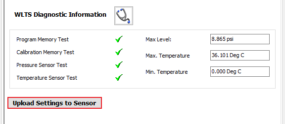
Figure 4: Upload new settings to WLTS.
- Disconnect from the utility and connect the sensor directly to the data logger. Use the SDI-12 utility in the CONNECT software to confirm SDI-12 communication:
3. Automatic Sensor Detection
After adjusting the interface and confirming SDI-12 communication, the sensor and its parameters can be programmed onto the logger via automatic detection. The user must create a Generic SDI-12 script through the NexSens CONNECT software to communicate and gather measurements. For proper configuration, the user must reference the sensor’s SDI-12 address (default=0).
SDI-12 Script Generation
- Create a Generic SDI-12 Script in CONNECT
- By default, the sensor outputs temperature (°C) first, followed by level (m).
- Units shown in the software must match the units in the script.
| Manufacturer | Model | SDI-12 Address | Port* | Warmup | Measurement Command | Power |
| Generic | SDI-12 | 0-9 | P1 or P2 | 15 seconds | C | Switch |
*Note: P0 port is always full power on the X3 data logger.
Run the Sensor Detection
Once the script is created, transfer and enable it on the data logger.
Before running the sensor detection, ensure all sensors are connected to the data logger and set up correctly by following their integration guide. Sensor detections should only be performed after all sensors are ready for programming.