
X3 Data Logger User Guide
Overview
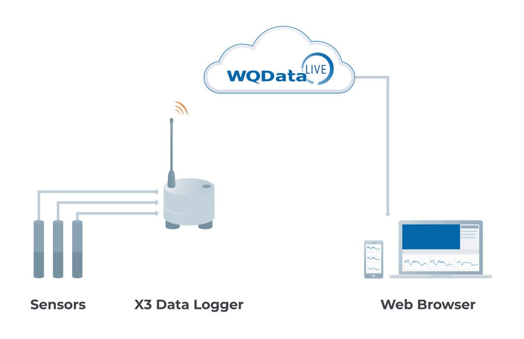
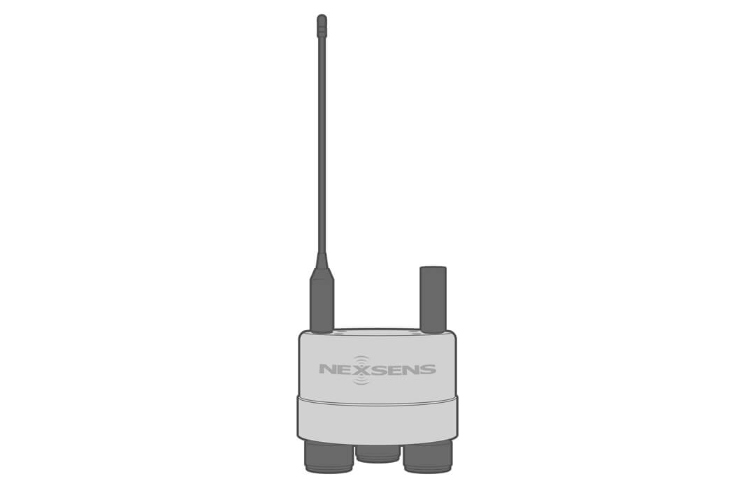
The NexSens X3 Environmental Data Logger connects sensors to WQData LIVE through 4G cellular, Iridium satellite, or WiFi. It features the industry’s largest multi-vendor sensor library and easy plug-in sensors.
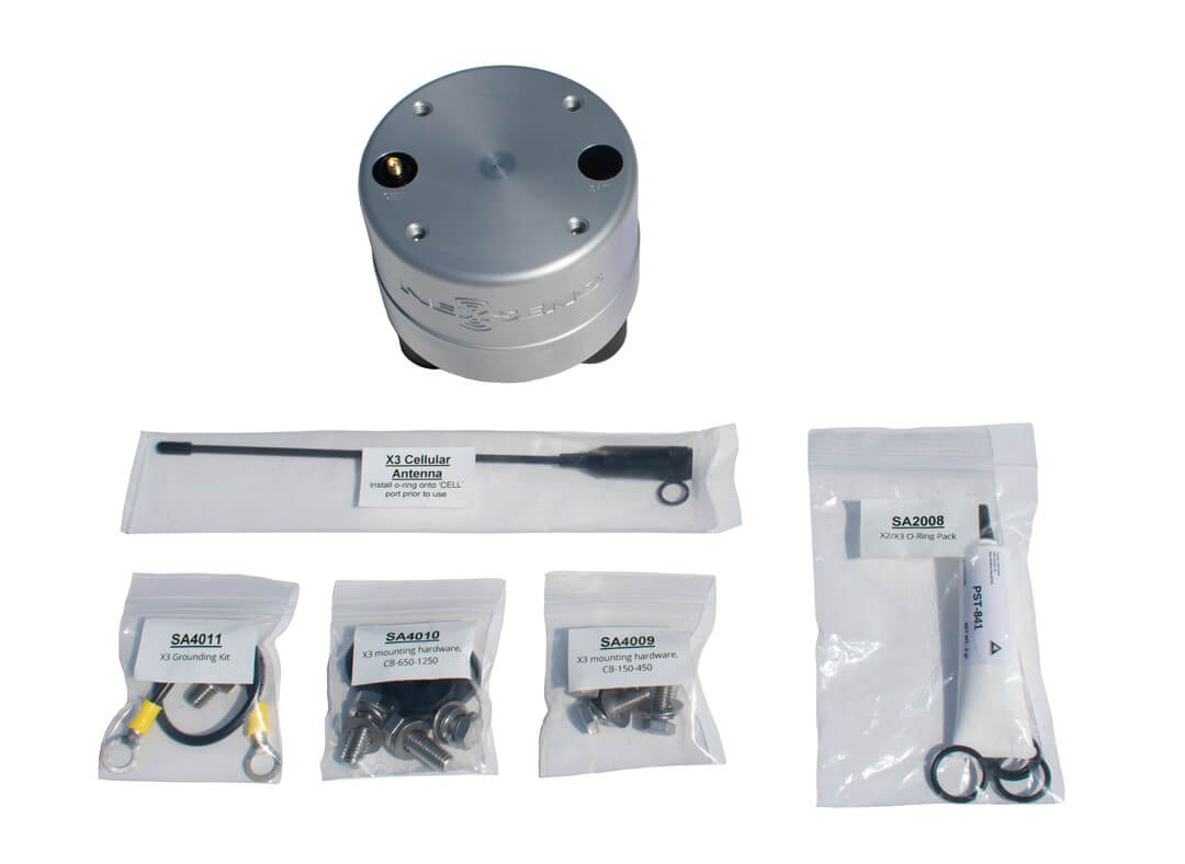
What’s in the Box?
- (1) X3 Environmental Data Logger
- (1) Grounding kit
- (1) Small buoy mounting kit
- (1) Large buoy mounting kit
- (3) Sensor port plugs, spare o-rings
- (1) Power port plug, spare o-ring
- (1) O-ring grease
- (1) Antenna (for cellular and Iridium telemetry); (2) Antennas (for cellular with Iridium fallback)
Mechanical
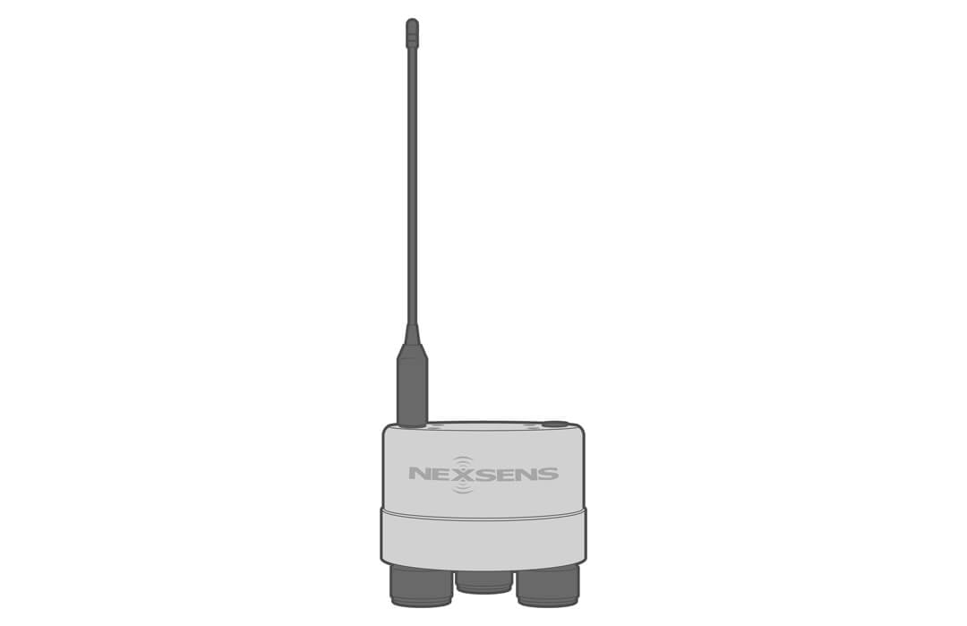
The X3 is a rugged data logging platform built for extreme environments and easy deployment. Fabricated from marine-grade aluminum, the housing is anodized to MIL specifications for superior resistance to corrosion, abrasion, and wear. It operates from -40°C to 70°C, withstands temporary 1-meter submersion, and features o-ring and epoxy-sealed ports.
Dimensional drawings available online.
![]()
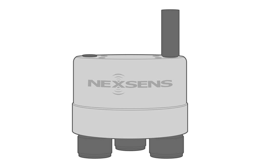
Electrical
The X3 can be powered with any 10.7 to 16.8 VDC supply. It includes reverse polarity protection, reverse current protection, and over current protection.
With a quiescent current of 450 uA, the data logger can work with 12VDC batteries, solar power systems, and AC power adaptors via the UW6 power cable.
A low active current of 55mA with telemetry transmissions ranging from 100mA (WiFi) to 300mA (cellular) provides efficiency for smart power management strategies.
Electrical specifications available online.
![]()
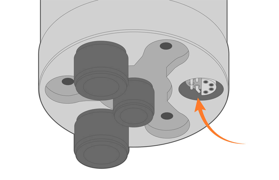
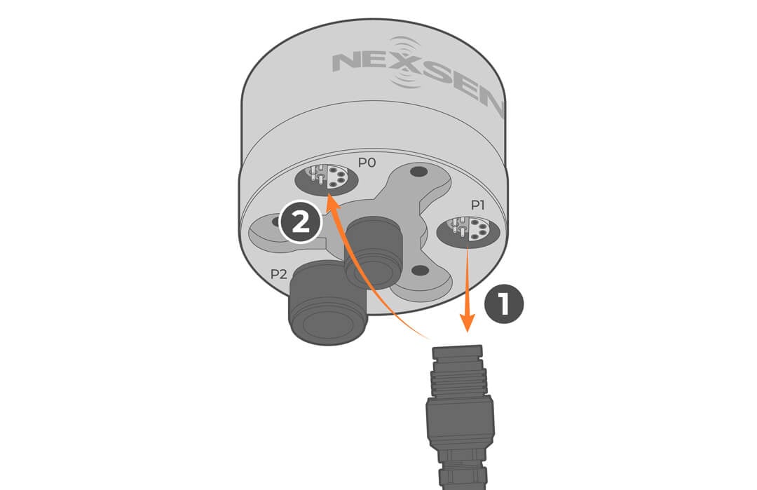
Connections
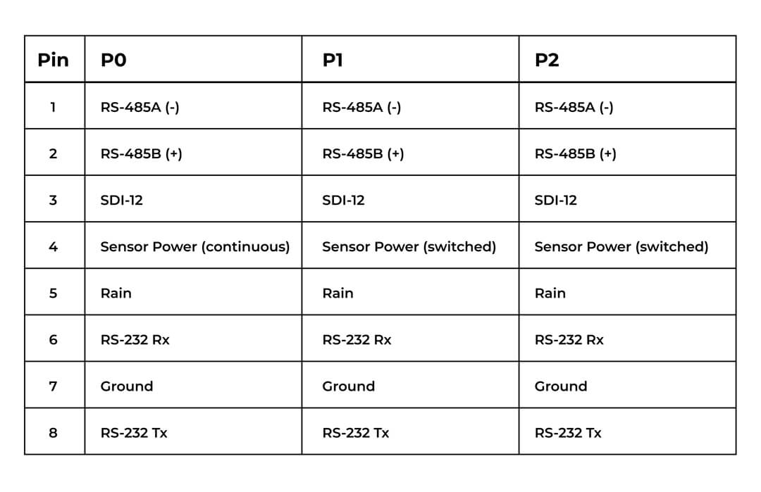
Three sensor interface ports (P0, P1, P2) and a power/communication port are available on the bottom of the X3.
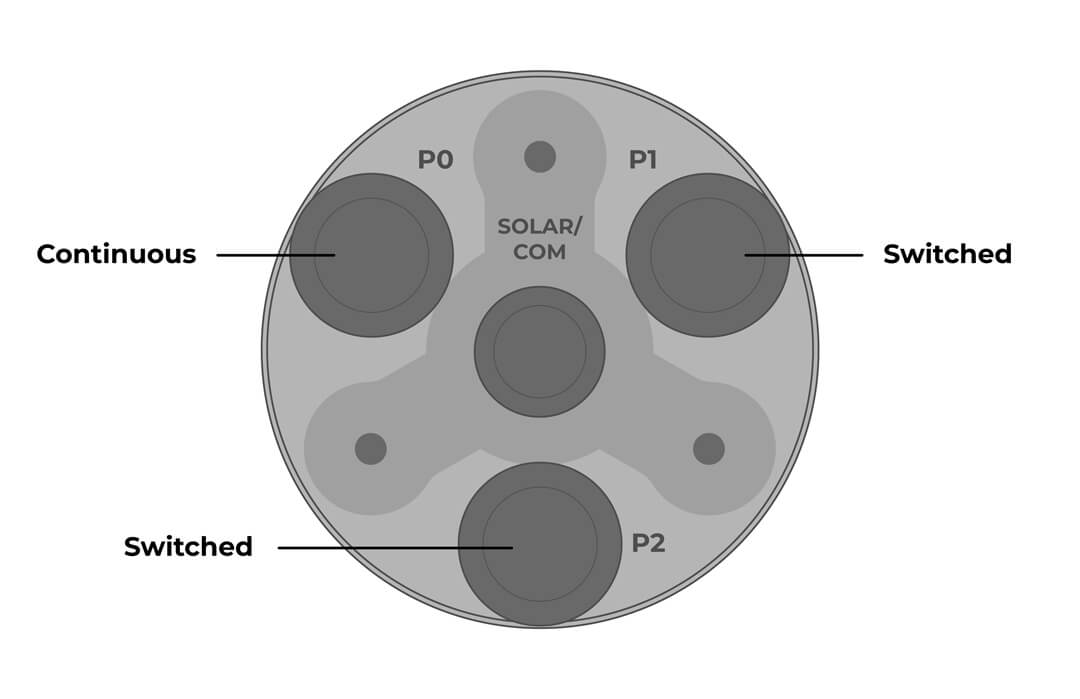
Continuous – Power is applied continuously. Ideal for weather stations, wave sensors, and ADCPs
Switch – Power is applied only when the sample interval is scheduled. Ideal for water quality sondes, temperature strings, and level sensors.
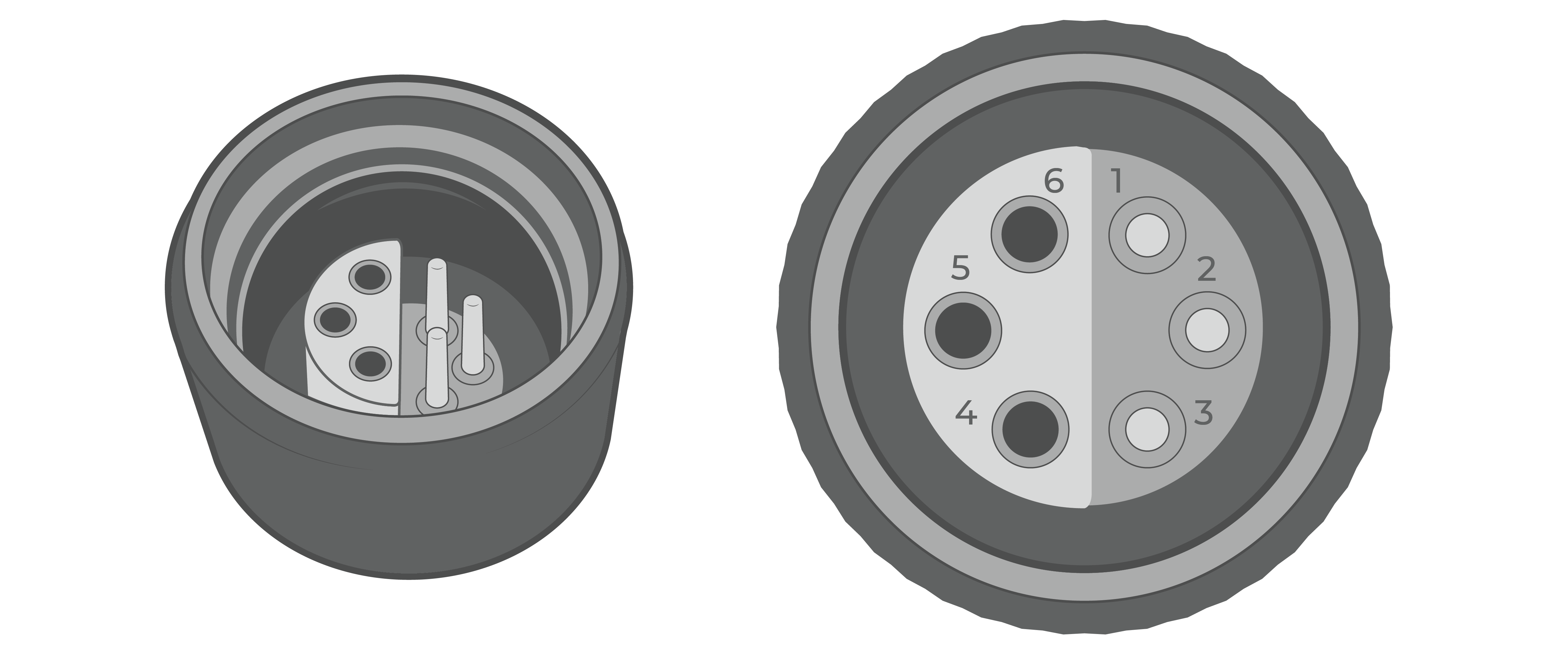
Sensor Port Pinout
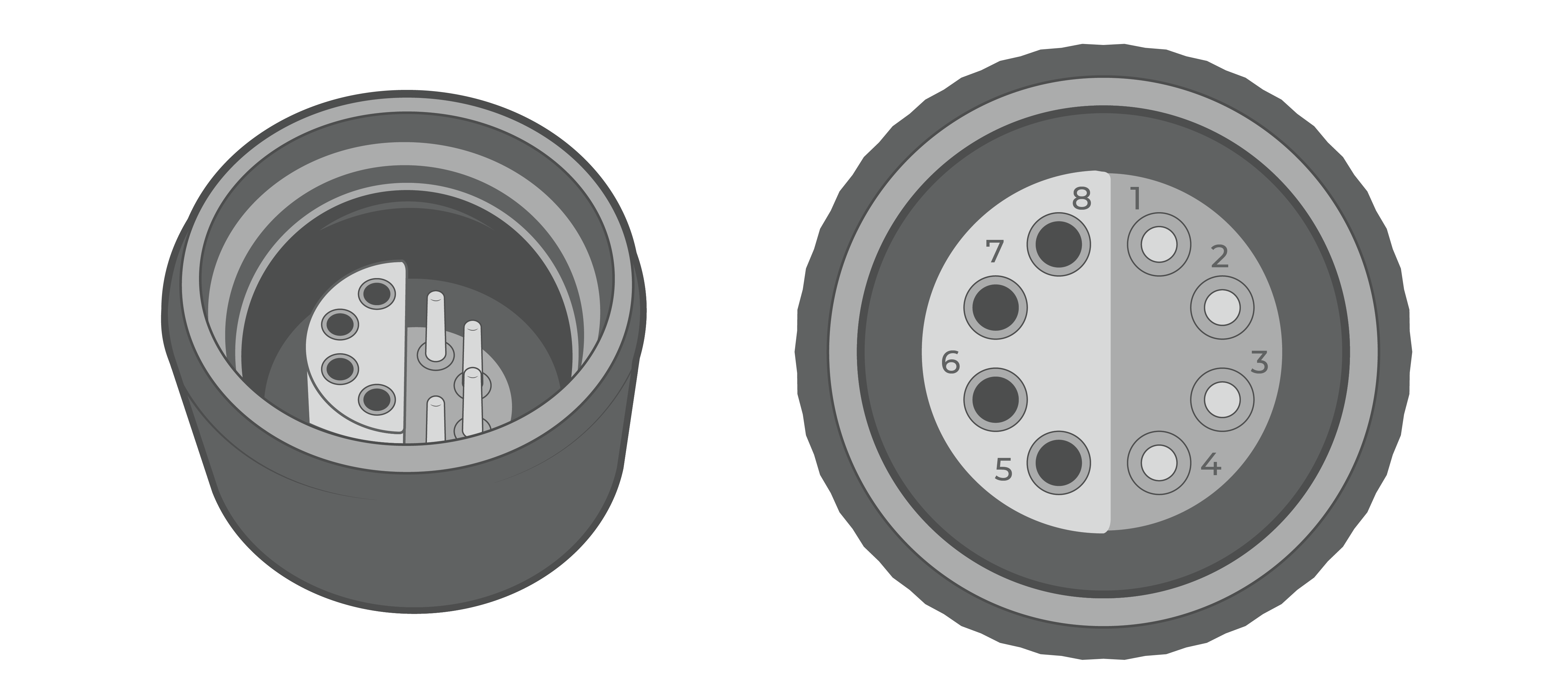
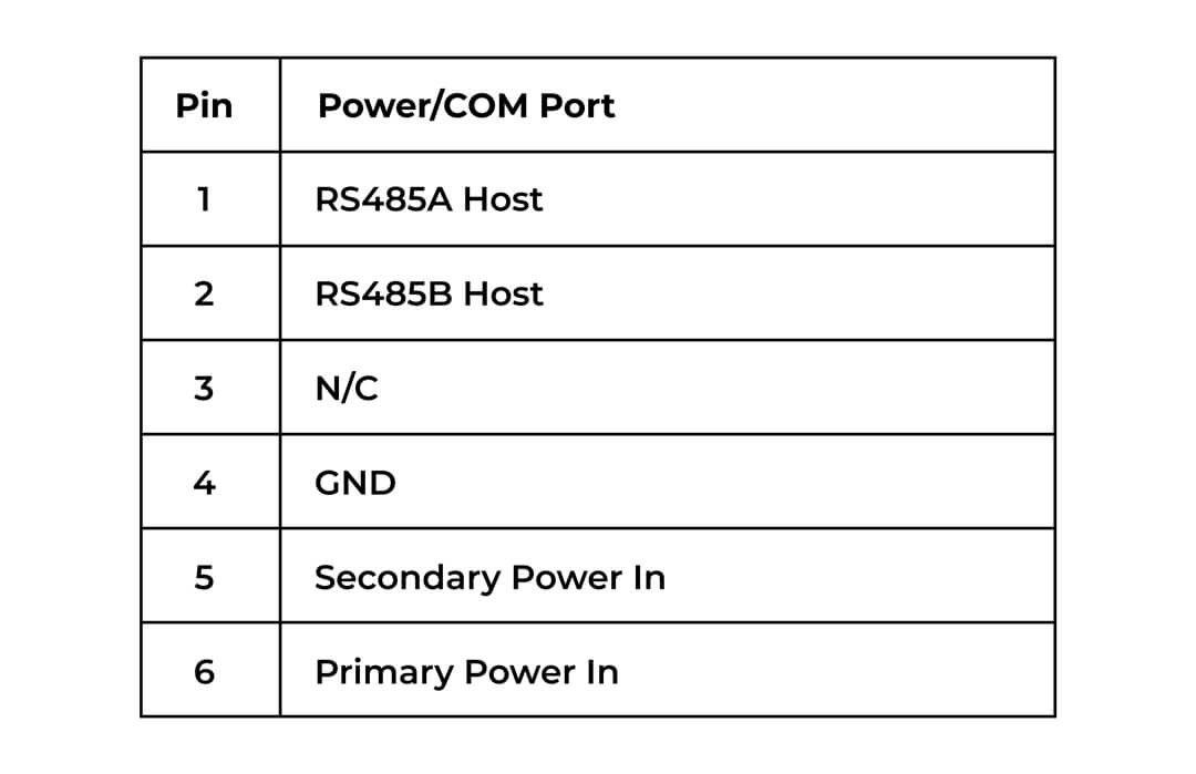
Power/COM Port Pinout
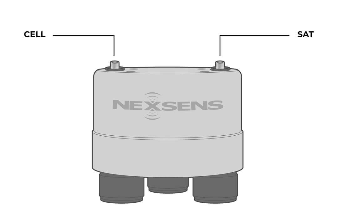
Antennas
Sealed SMA antenna ports are preinstalled when ordered with cellular and/or Iridium telemetry. The Wi-Fi antenna is internal.
Each telemetry type will have a unique setup protocol. Use the links below to navigate to each guide.
 |
 |
| Cellular antenna specifications | Iridium antenna specifications |
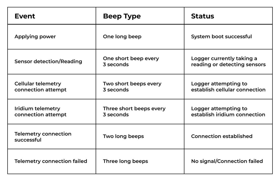
Beep Indicators
Once plugged in, the X3 data logger will start to beep. Each Beep Type coincides with a specific event–see the table below for reference.
Operation
Sensor Interface
The X3 supports sensors with the following interfaces: SDI-12, RS-485, and RS-232. Additionally, the logger is compatible with tipping bucket rain gauge inputs. Sensors can be plugged into any of the ports, regardless of communication protocol.
CONNECT Software
CONNECT Software is the direct connect method to communicate with the X3. Users can easily add sensor profiles, set intervals, read/upload measurements, and set up telemetry. The software also includes tools for troubleshooting.
Sensor Library
The preloaded sensor library is located in CONNECT Software and WQData LIVE. The library includes sensors that are compatible with the X3 data logger, with a pre-set sensor profile that can be adjusted as needed for each project.
The library contains hundreds of sensors from leading manufacturers:
| Aandera | In-Situ | Sequoia Scientific |
| Airmar | Intellect Water | Shark Marine |
| AML | OceanographicINW | SonTek |
| APG | Li-Cor | Sporian Microsystems |
| Campbell | Lufft | Stevens Water |
| Design Analysis | NexSens | Teledyne RDI |
| EchoLogger | Observator | Trimble |
| Eureka | OTT | TriOS |
| FloWav | Ponsel | Tritech |
| FTS | Proteus Instruments | Turner Designs |
| Garmin | RM Young | Vaisala |
| Geolux | s::can | Van Essen Instruments |
| Gill Instruments | Satlantic | VEGA |
| Global Water | Sea-Bird | WaterLOG |
| Greyline | Seametrics | WET Labs |
| Hach | Senix | YSI |
| Hydrolab | Sentek | And many more… |
Don’t see a manufacturer? Contact a systems specialist for support.
WQData LIVE
WQData LIVE is the secure cloud datacenter for easily accessing the data from the X3. The interface allows for remote troubleshooting and configuration of the X3 data logger.
Users can access interactive tools to view and share data, set up custom dashboards for data viewing, create alarms, and generate reports.
Note: The X3 collects data in UTC, and the local timezone can be adjusted in your WQData LIVE account.
WQData LIVE Setup
Before connecting any sensors to the logger, set up the project in WQData LIVE.
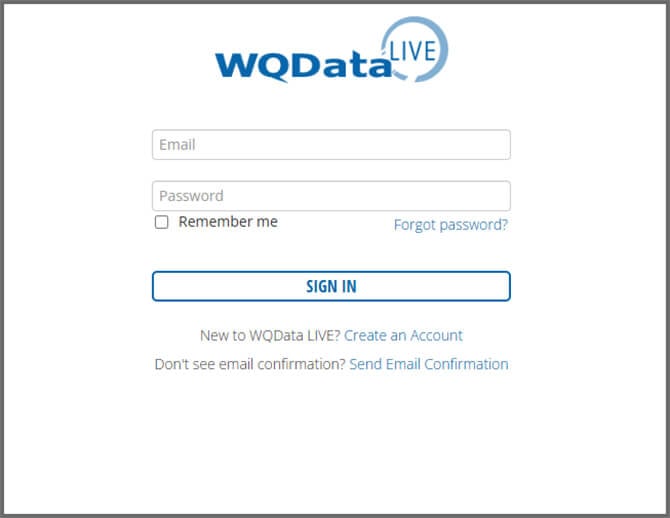
- Sign in or create a WQData LIVE account.

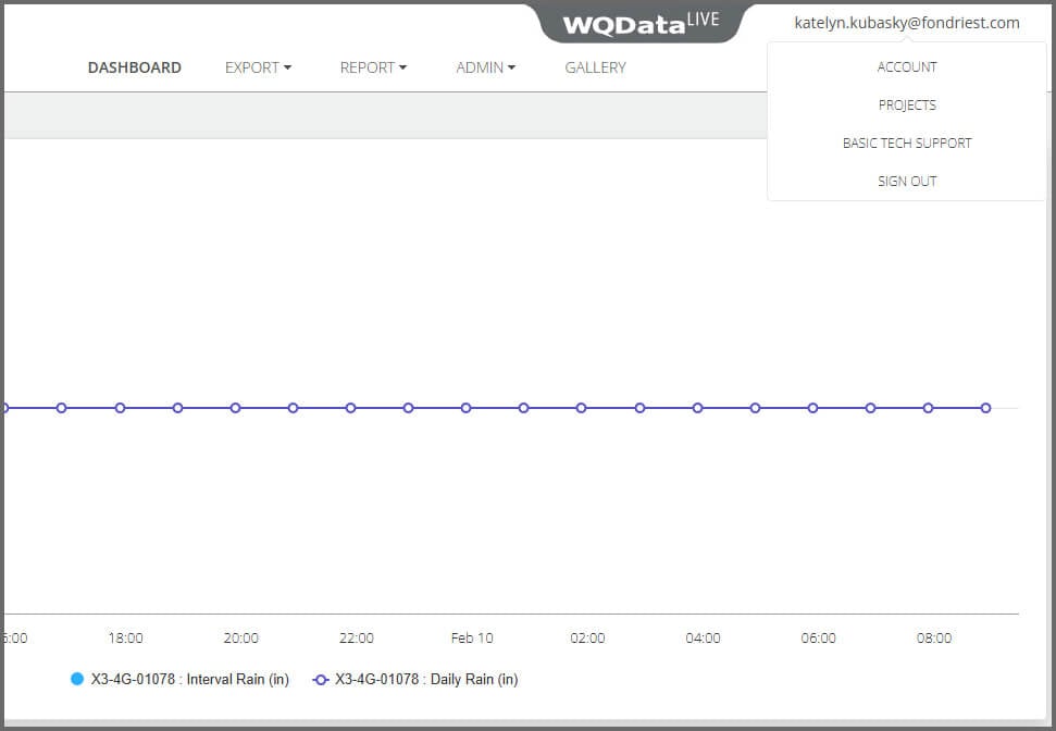
- Hover over the email in the upper right-hand corner of the page and select PROJECTS from the drop-down menu.

- Click Create New Project and complete the project setup.

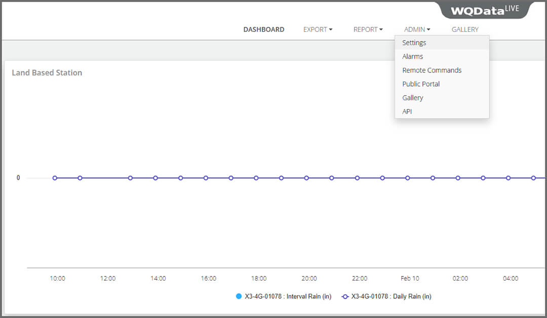
- Go to ADMIN | Settings and create a site.

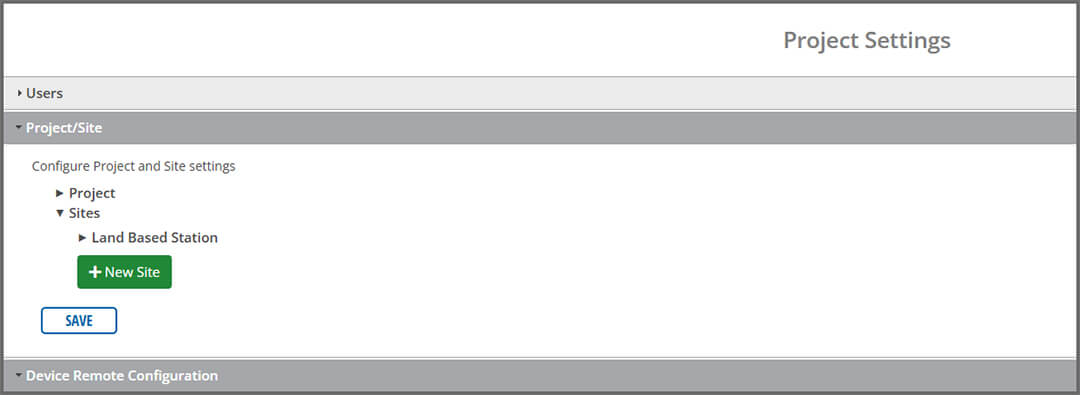

- Once the site is created, enter the device’s claim code (found in the shipping documents) and then save.
Telemetry
After completing project setup in WQData LIVE, follow the instructions below to enable the appropriate telemetry communication. Only configure the telemetry type(s) that will be used in the field.
Each telemetry type will have a unique setup protocol. Use the links below to navigate to each guide.
Wi-Fi
Wi-Fi telemetry comes standard on all NexSens X3 data loggers and can be used as the primary telemetry option in areas with internet access. The X3 wifi is 2.4GHz b/g/n and supports WPA2 and WPA3 Personal.
- Supports 2.4 GHz Wi-Fi networks (802.11 b/g/n)
- Compatible security types:
- WPA2 Personal
- WPA3 Personal
- Open (unencrypted networks)
Note (Open Networks): When connecting to an Open Network, CONNECT software requires a value in the password field to save the configuration. Enter a placeholder value (e.g., 12345678). Open Networks do not use a password, and the entered value will not affect connectivity.
Recommendation: For best security and reliability, use WPA3 Personal (preferred) or WPA2 Personal networks whenever possible.
Connecting to Wi-Fi
- Connect the X3 logger to a PC and launch CONNECT software.
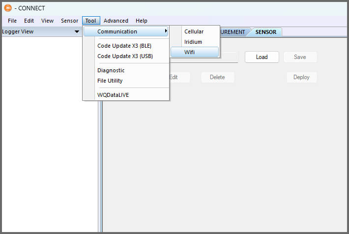
- Navigate to Tool | Communication | Wifi within CONNECT.

- Select the Scan option at the bottom of the Wi-Fi interface, and a list of available networks will populate.
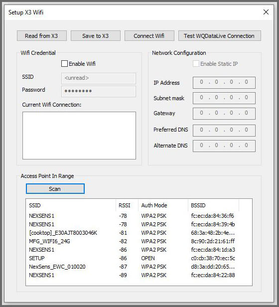

- The Received Signal Strength Indicator (RSSI) refers to the signal strength of the specific network.
- -65 to -70: Provides a reliable connection.
- -71 to -79: Minimum level for a reliable connection.
- -80 to -84: May result in intermittent connectivity.
- -85 to -89: Absolute minimum to get connections periodically.
- -90 or lower: Unreliable signal.
- The Received Signal Strength Indicator (RSSI) refers to the signal strength of the specific network.
- Note the SSID of the network you would like to connect to.
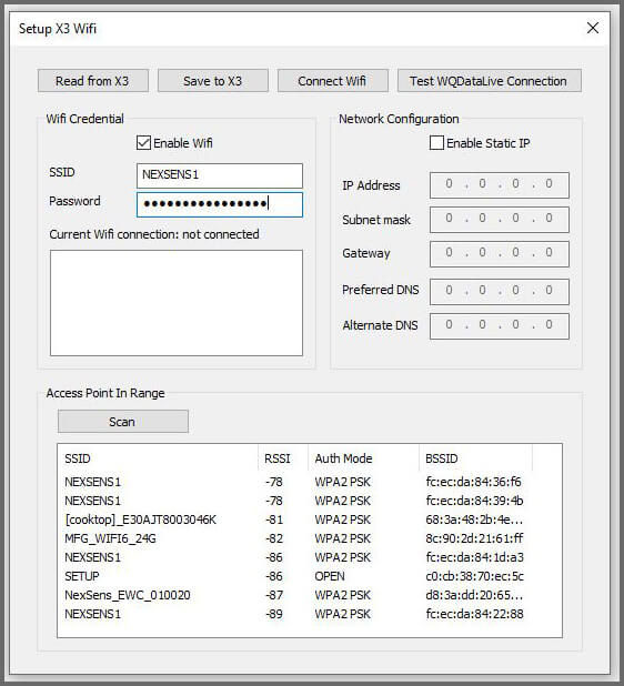
- Select Read from X3 to view the current Wi-Fi configuration. For new loggers, check the Enable Wifi option and enter the network’s SSID and Password. Then select Save to X3.

- A confirmation message will appear once the network has been saved.
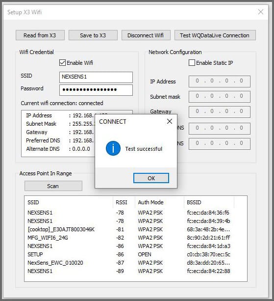
Confirm Connection
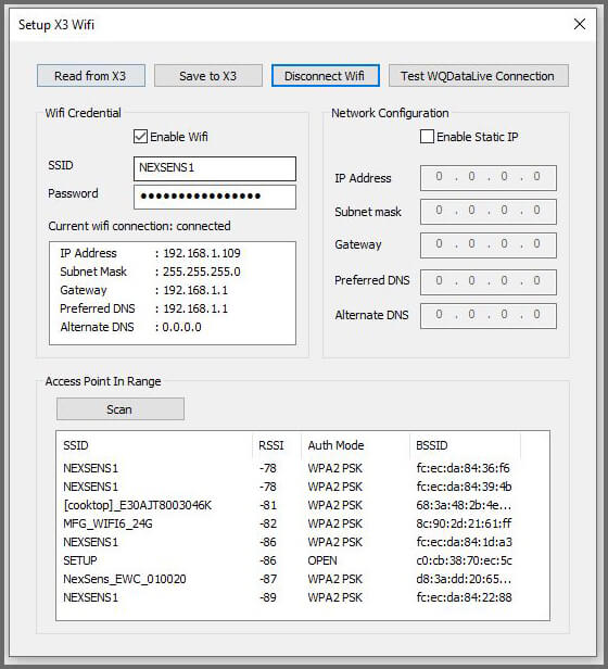
- Test Wi-Fi connectivity by selecting Connect Wifi at the top of the interface.
- A successful connection will show the Wi-Fi connection characteristics (i.e., IP address, Subnet Mask, Gateway, Preferred DNS, and Alternate DNS) and display Current wifi connection: connected.
- A successful connection will show the Wi-Fi connection characteristics (i.e., IP address, Subnet Mask, Gateway, Preferred DNS, and Alternate DNS) and display Current wifi connection: connected.
- Select Test WQDataLive Connection to confirm the device can communicate with WQData LIVE. A prompt will display for a successful connection.

Add Sensors in CONNECT Software
Using the appropriate integration guides for your sensor suite, complete the system setup in CONNECT.
Cellular
Cellular plans for the X3 data logger can be provided and managed by NexSens Technology or through a separate provider. If the cellular plan was purchased through NexSens, the logger will arrive already set up for transmissions. Skip ahead to Add Sensors in CONNECT.
If using a different cellular provider, users will need to complete additional steps during setup. Contact NexSens support for help.
Add Sensors in CONNECT Software
Using the appropriate integration guides for your sensor suite, complete the system setup in CONNECT.
Iridium
Iridium data plans for the X3 data logger can be provided and managed by NexSens Technology or through a separate provider. If the plan was purchased through NexSens, the logger will arrive already set up for transmissions. Skip ahead to Add Sensors in CONNECT.
If using a different Iridium provider, users will need to complete additional steps during setup. Contact NexSens support for help.
Add Sensors in CONNECT Software
Using the appropriate integration guides for your sensor suite, complete the system setup in CONNECT.
Set Transmit Flags
Transmit flags control the amount of data transmitted to WQData LIVE. It is important to review your iridium plan to ensure the data size does not exceed the allowable limit.
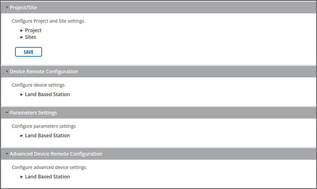
- Open WQData LIVE and navigate to the ADMIN | Settings tab at the top of the dashboard.
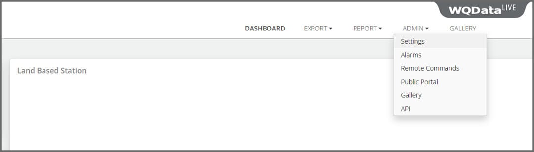

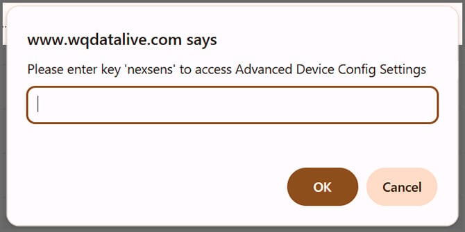
- Click on the Advanced Device Remote Configuration drop-down menu and choose the logger.


- Enter code “nexsens” when prompted.


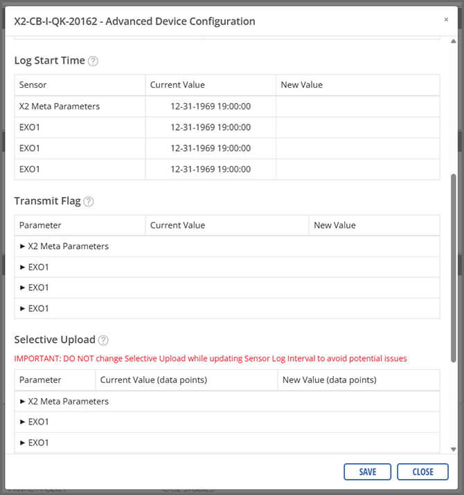
- Open the Transmit Flag dropdown.


- Enable the desired parameters.
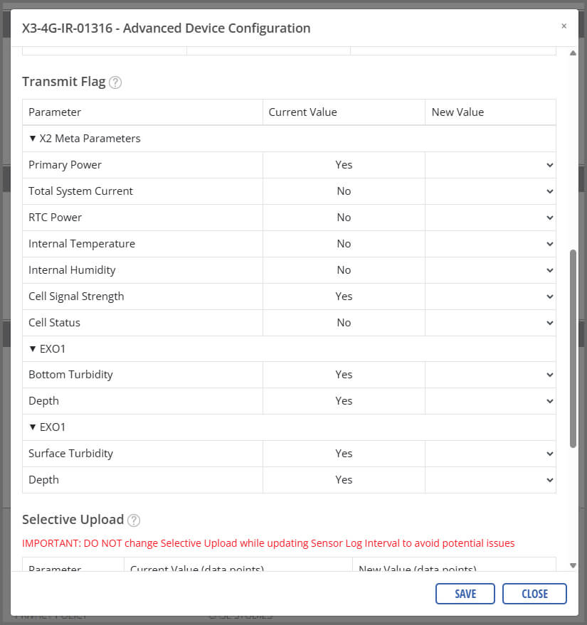

- Once complete, select Save.
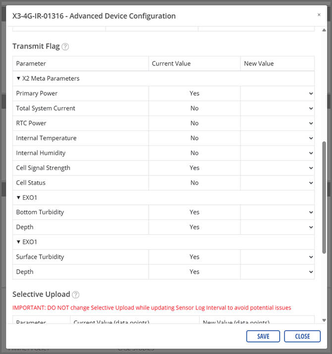
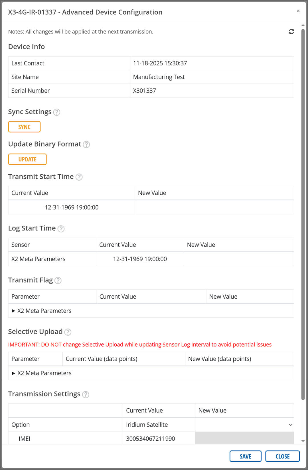
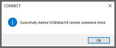
Send Binary Format Command
- In the Advanced Device Configuration, click UPDATE under the Update Binary Format section.
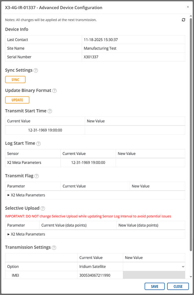

- A prompt should display showing that the command was sent successfully.


- After the command is sent, three full transmission intervals will occur before data is pushed to the web.
Iridium with Cellular Fallback
The X3-4G-IR defaults to 4G cellular and falls back to Iridium satellite when cellular service is not available. This ensures continuous data transmission when coverage is spotty or when equipment is moved in and out of coverage.
Complete Cellular and Iridium Setup
If the data plan(s) were purchased through NexSens, the X3-4G-IR will arrive already set up. Skip ahead to Add Sensors in CONNECT.
If using a different provider, users will need to complete additional steps during setup. Contact NexSens support for help.
Add Sensors in CONNECT Software
Using the appropriate integration guides for your sensor suite, complete the system setup in CONNECT.
Set Transmit Flags
Transmit flags control the amount of data transmitted to WQData LIVE. It is important to review your iridium plan to ensure the data size does not exceed the allowable limit.
- Open WQData LIVE and navigate to the ADMIN | Settings tab at the top of the dashboard.

- Click on the Advanced Device Remote Configuration drop-down menu and choose the logger.
- Enter code “nexsens” when prompted.
- Open the Transmit Flag dropdown.
- Enable the desired parameters.
- Once complete, select Save.
Send Binary Format Command
- In the Advanced Device Configuration, click UPDATE under the Update Binary Format section.
- A prompt should display showing that the command was sent successfully.
- After the command is sent, three full transmission intervals will occur before data is pushed to the web.
Field Installation
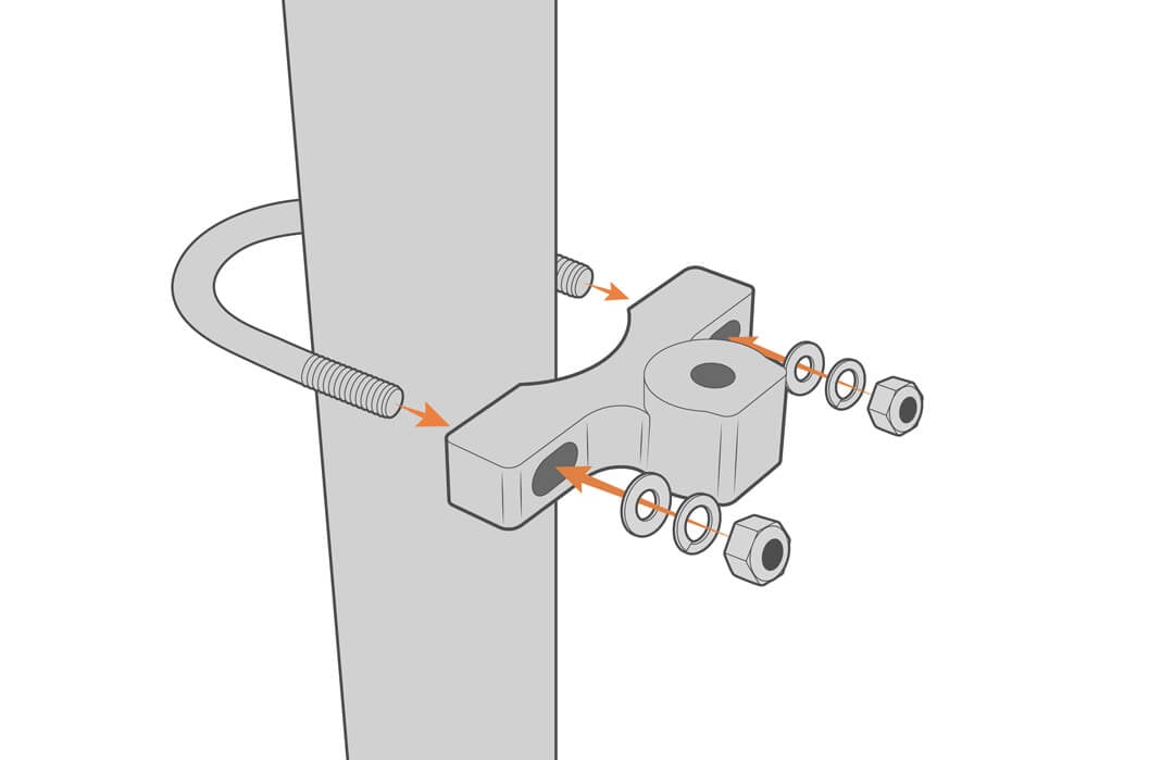
Mounting
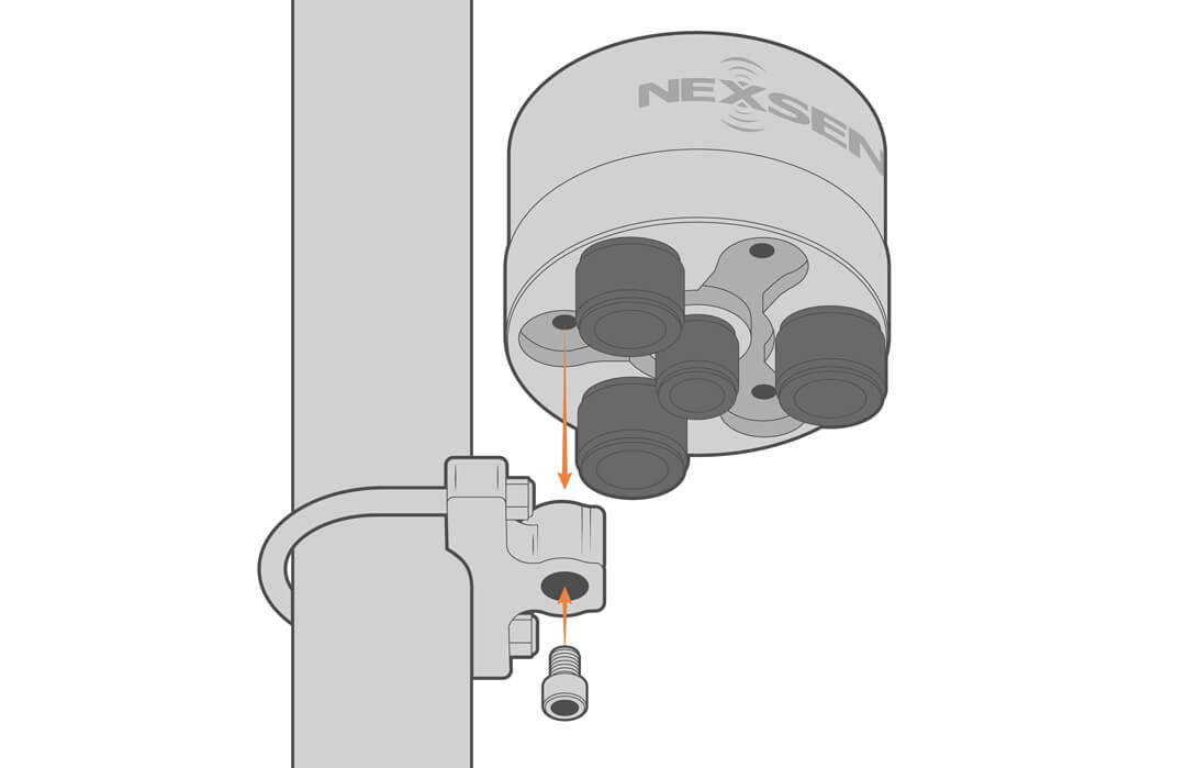
The X3 can be mounted from its top with four threaded holes or from the bottom with any of the three threaded holes. The PM2 mount kit facilitates mounting to masts, poles and walls.
- Secure the mounting kit to a pole using the included hardware.

- Attach the logger.
- Install the antenna in the correctly labeled port (i.e., CELL or SAT).
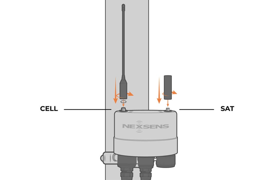
- Ensure the cellular antenna’s O-ring is seated correctly, and the antenna is making solid contact with it.
For data buoys, view the appropriate User Guide in the Knowledge Base for mounting instructions.
Grounding
Grounding the X3 helps prevent damage from voltage surges, electrical lines, lightning strikes, or electrostatic discharge (ESD).
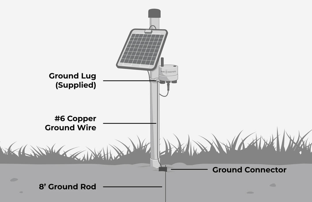
Grounding in Land Applications
A grounding kit is included with each X-Series data logger. Always follow the guidelines of the National Electrical Code (NEC) for safety.
For best results, use a separately purchased 8 ft ground rod and #6 copper wire with the supplied ground lug, as shown.
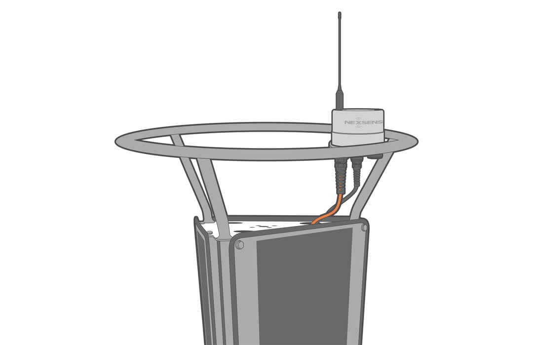
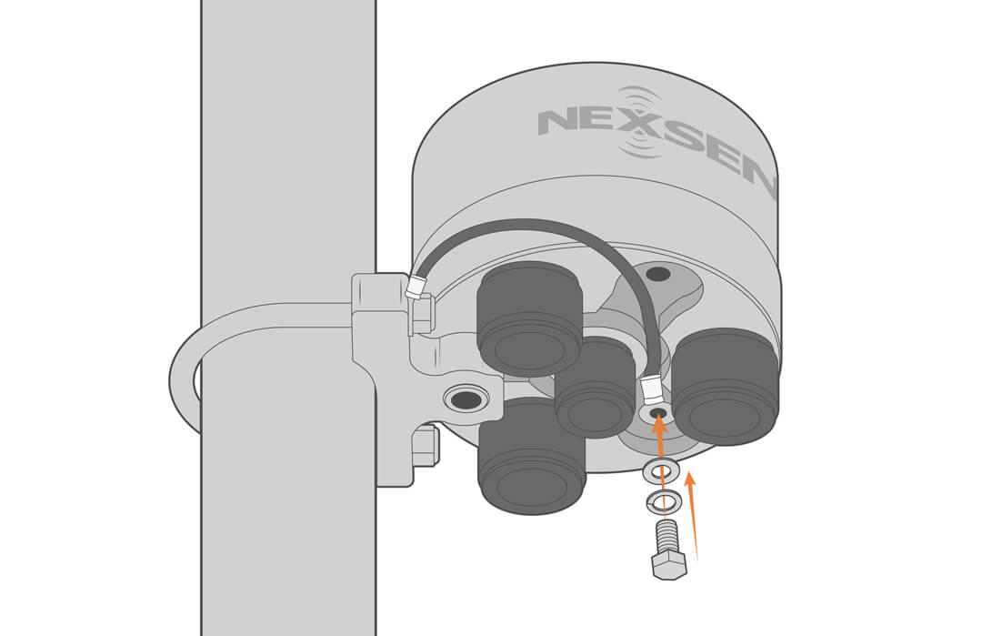
For well-grounded towers and masts, use the supplied ground kit, as shown.
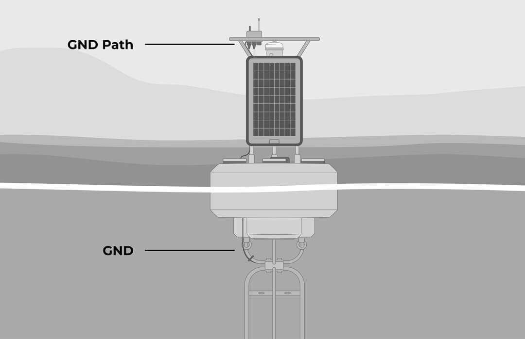
Grounding in Open Water Applications
For offshore applications, grounding to the water is the only option, although many buoy systems go ungrounded. If needed, an electrical ground wire should be connected to the X3 and the buoy hull metal frame.
On large platform buoys, the X3 housing is grounded to the tower ring plate and to the tower when mounted in place. This connects the logger housing to water through the buoy frame.
Maintenance
As a general practice, measurement data, battery voltage, and other diagnostics (humidity, telemetry signal strength, etc.) should be monitored daily. Alert notifications for data and system functions can be used to detect anomalies and provide early warning that maintenance is required.
Desiccant Replacement
Desiccant is used to absorb humidity and should be replaced annually, or anytime the logger is opened.
- Unthread the middle power port plug to release pressure.
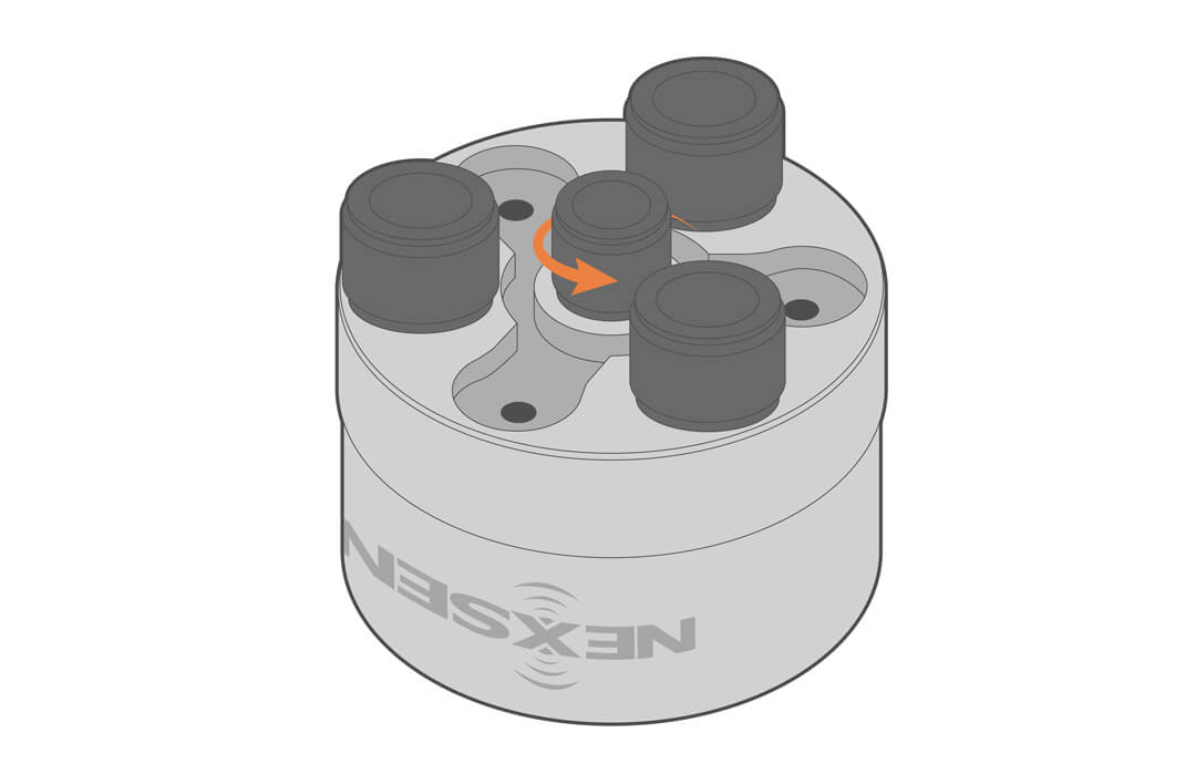
- Remove the wire from its track at the base of the data logger’s aluminum housing.
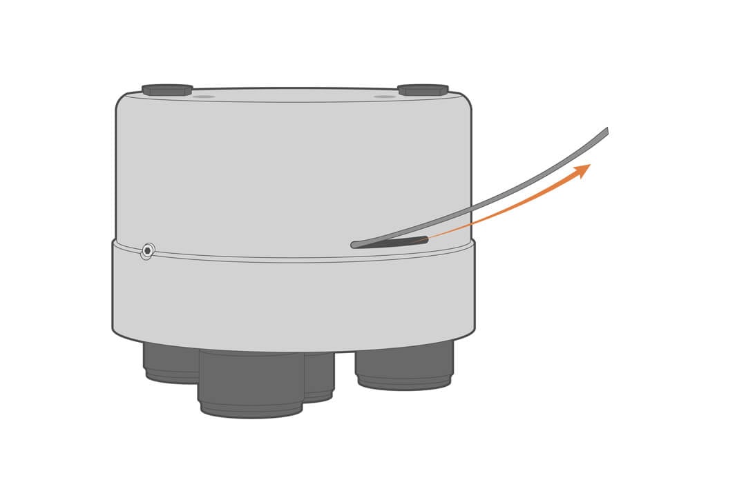
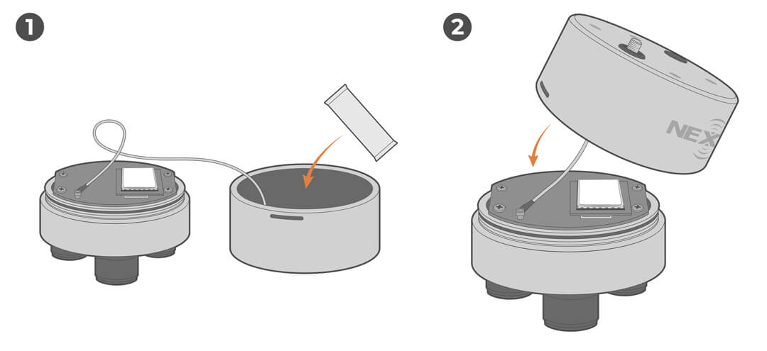
- Carefully remove the lid, taking care not to stress the wires.

- Replace the desiccant and reinstall the lid.

- Reinstall the wire and center port plug.

- Review the internal humidity readings on WQData LIVE.
- Ideally, the internal humidity will stabilize under 20%; however, humidity levels will be dependent on the environmental conditions.
Storage
When storing the X3 data logger for an extended period of time, follow the steps below to preserve system function and prevent damage.
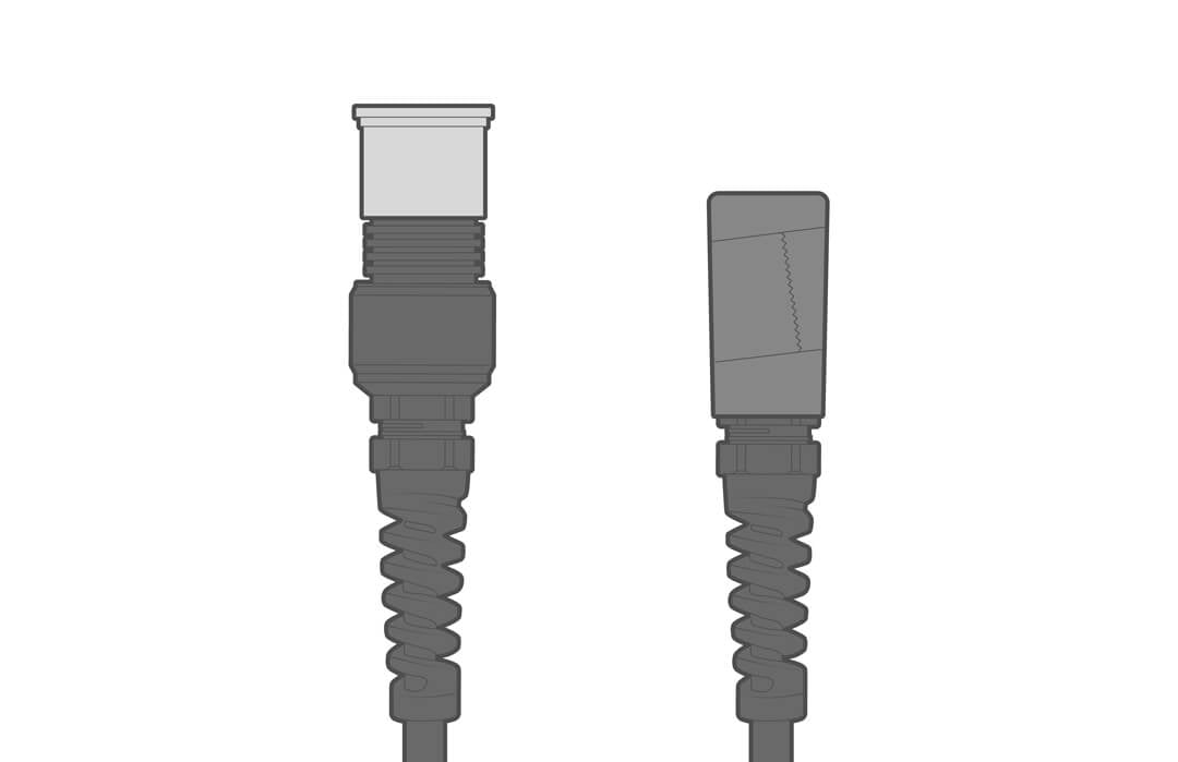
- Disconnect the center port cable and replace it with a port cap.
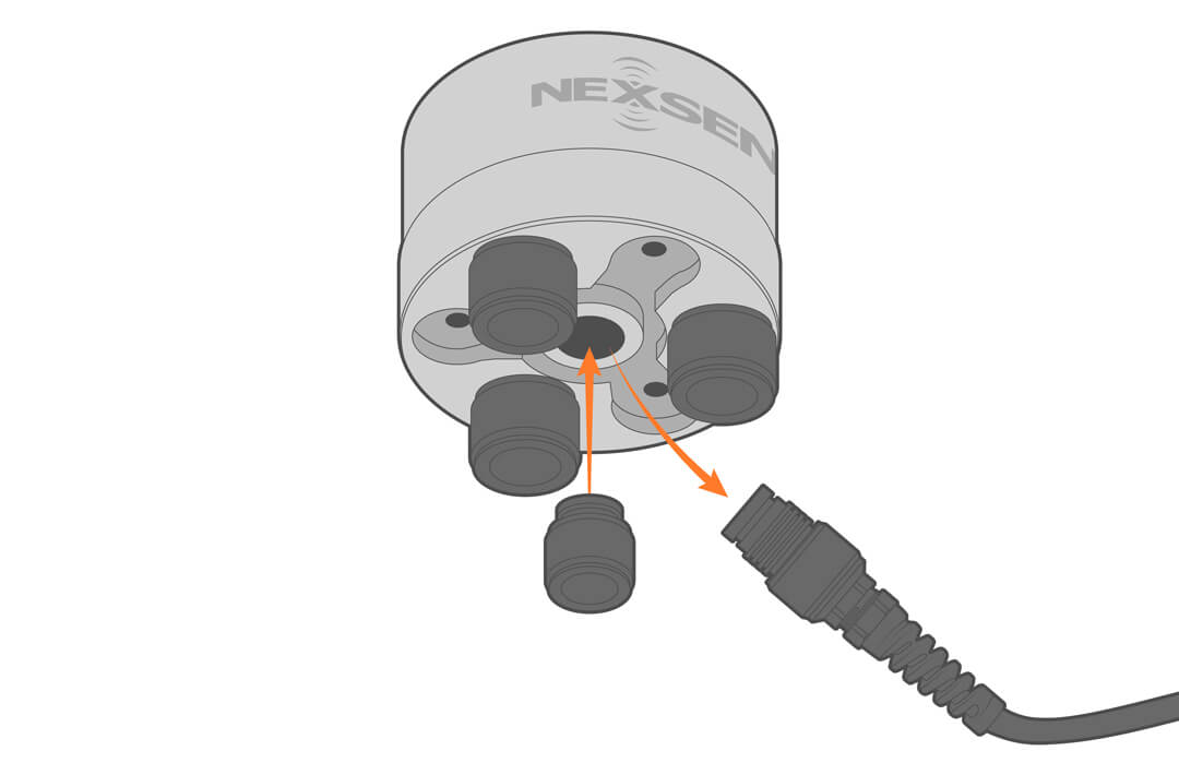
- Use the O-ring grease included in the maintenance kit as needed to re-grease the cable/plug connector O-rings.
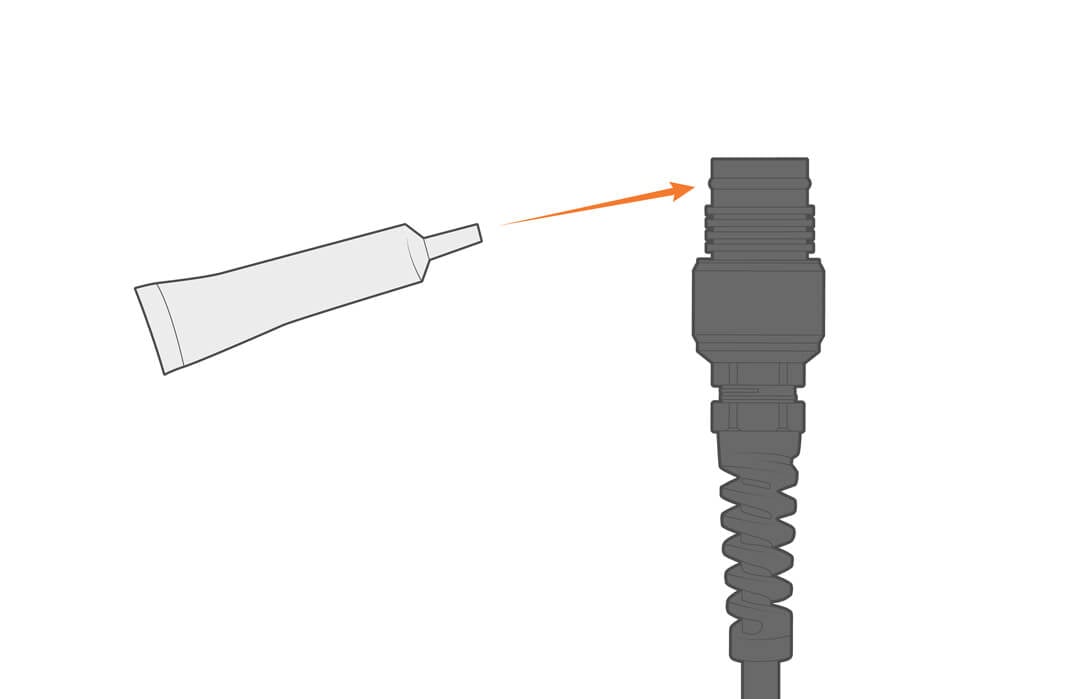
- Inspect all sensor ports and cable connections, ensuring there are no signs of moisture or damage.
- Cover all logger or cable connectors with a dust cap or UW-plug.
- Store the loggers and accessories in a dry, climate-controlled environment.
Troubleshooting
If you encounter issues while using the NexSens X3 data logger, refer to the appropriate troubleshooting procedure in this section for guidance. The steps below are designed to help identify and resolve common problems quickly.
For additional help, contact a NexSens systems specialist.
Troubleshooting Telemetry Connection
If a NexSens X-Series data logging system suddenly stops sending data to WQData LIVE, follow the steps in the video below to resolve the issue. For written instructions, skip ahead to Review Last Contact Time.
Review Last Contact Time
First, check the system on WQData LIVE to learn more about the problem.
- Check the Last Contact Time for the logger. This indicates whether the system has contacted the web at the expected time.
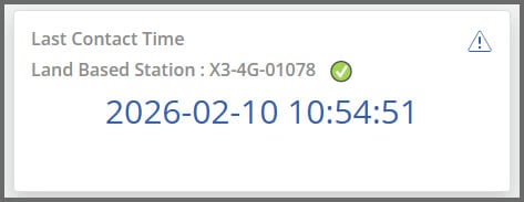

- There are three possible icons:
Icon Explanation Potential Reasons for Missing Data 

Logger is contacting as expected. Data is missing due to a loss of sensor connection, not due to telemetry issues. 
Logger has missed its latest transmission. Intermittent connectivity. Wait for the next interval to see if the connection is restored. 
Logger has missed multiple transmissions. Loss of connectivity. - If you see the green icon, view the Troubleshooting Loss of Sensor Communication section for help.
- If red, continue to the next step.
Review Internal Diagnostics
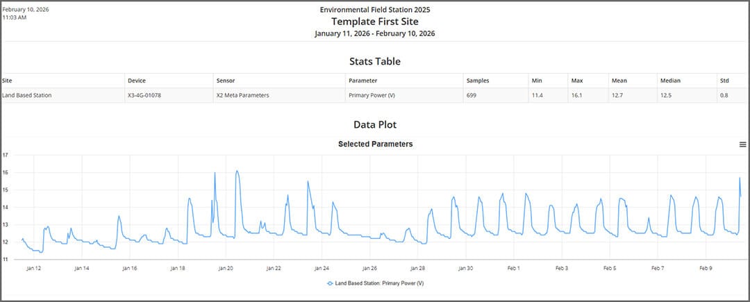
X-Series data loggers collect power, humidity, and signal parameters that display the health of the system. Use WQData LIVE’s reporting tool to review diagnostic data collected by the logger.
Primary Power
- Healthy systems will show primary power typically ranging from 12.5 to 14.5 V.
- If the primary power has dropped below 11.5V, that is the likely cause of the telemetry outage.
- Review the appropriate documents in the Knowledge Base to troubleshoot the solar power pack.

- Review the appropriate documents in the Knowledge Base to troubleshoot the solar power pack.
Internal Humidity
High humidity can adversely impact or damage the electronics. Internal humidity should be below 50%. A high humidity or sudden spike indicates that water has breached the housing, and the logger will need to be sent to the factory for evaluation and repair.
Signal Strength/Status
The signal strength provides an indication of how stable the telemetry connection is at the deployment site.
- Below are stable signal strength values for each telemetry type:
- Wi-Fi: -30 to -60 dB
- Cellular: -51 to -75 dB
- Iridium: 3-5 dB
- If the signal strength is outside of these ranges, the connection may be intermittent or failing.
- If signal strength values have changed abruptly or there is an increase in signal status errors, a visual inspection of the antenna is required.
Check with Telemetry Provider
If the internal diagnostics do not indicate the telemetry issues, check with the telemetry provider to ensure the service is still active and that no changes have been made.
Visual Inspection
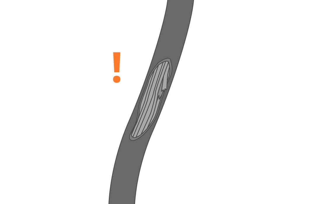
Most often, lost communication issues will result in a field visit for on-site troubleshooting.
- Inspect the system for damage from weather events, vandalism, and wildlife.
- Check antenna for damage or water ingress at the connector. Dry and reinstall antenna with o-rings in place
- Check for tree cover and other solar obstructions—reposition or clear as needed.
- Check all connectors and cables for water ingress, cuts, chafing or loose connections.
- If the system appears to be intact, unplug and wait 30 seconds before plugging the power back in and listen for audible signals.
- If silent, the solar power and/or battery may have failed and needs to be repaired or replaced.
- Connect sensors to the manufacturer’s software and confirm proper function.
- Another possible cause could be that the cellular SIM may have failed or is disconnected. Contact NexSens or your cellular service provider.
Direct Software Connection
If communication has not been reestablished and there are no visual or power issues, direct connection to the logger will allow users to adjust settings and, if needed, change cellular service providers.
- Plug the X3 into a computer and launch CONNECT software.
- Open the Cellular settings and turn the RTU board on.
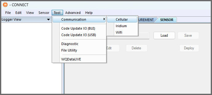

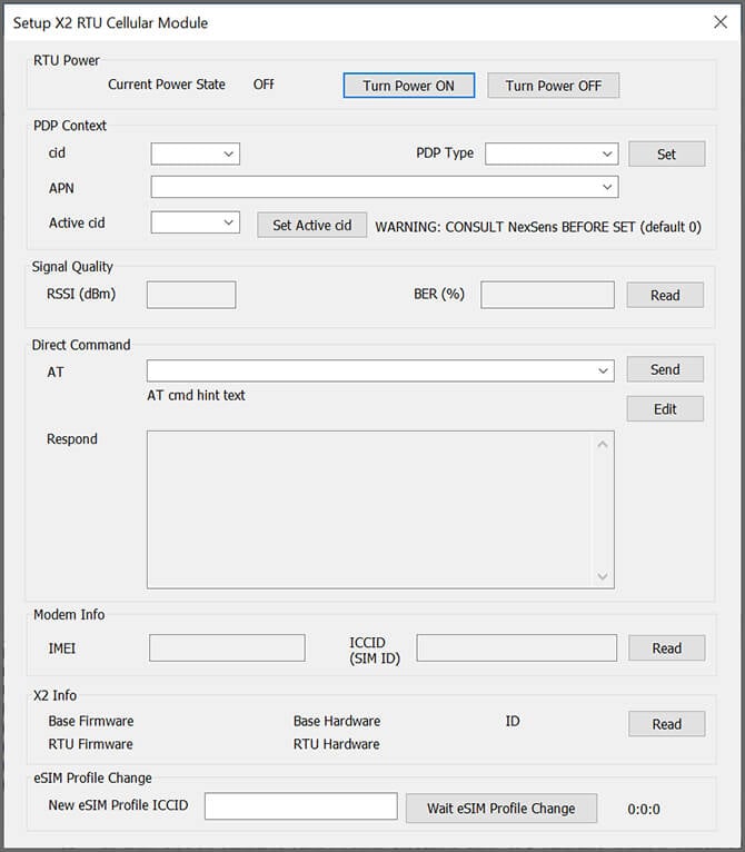

- If the RTU board does not power on, try again. After multiple attempts, it is likely the modem has failed and needs to be replaced.
- If it does power on, verify signal strength and stability by testing connectivity.
- Review and edit (if necessary) the Custom 1 command, and then click Send.
If You See… Do This… IP address returned after AT#SGACT Connection successful – proceed to Custom 2 command “SIM not inserted” Power down the system and reinsert the SIM “Activation Failed” Review PDP Context settings. If correct, contact the carrier to ensure the plan is active and set for an M2M plan. “Requested Service Option not subscribed” Contact the carrier to ensure the plan is active and set for an M2M plan. “Unspecified GPRS error” Check carrier compatibility with modem/antenna bands - If a successful Custom 1 command response is returned, continue to the Custom 2 command and select Send.
- Reconnect the system and try to establish communication with WQData LIVE.
Troubleshooting Loss of Sensor Communication
If a sensor is not communicating with the X3 data logger, follow the steps below to troubleshoot communications and get data back online.
Confirm Sensor Issue
First, users will need to rule out whether the issue is related to the sensor or a telemetry outage.
- In WQData LIVE, check the last contact time and primary power.
Icon Explanation Logger is contacting as expected. Logger has missed its latest transmission. Logger has missed multiple transmissions. - If you see the red icon, view the Troubleshooting Telemetry Connection section for help.
- If green, continue to the next step.
Check Power
- Check the power history using WQData’s reporting tool.
- Ensure the power is sufficient for operation.
- Refer to the sensor manual for power requirements.
- Refer to the sensor manual for power requirements.
Visual Inspection
- Visit the field site, inspect the sensor, cable connection, and power supply for physical damage.
- Reset the sensor by unplugging it from the logger, and plug it into P0.
- Confirm functionality on a computer.
- If communications are not restored, contact a NexSens systems specialist for help.
- 937-426-2703
- [email protected]
Troubleshooting a Drop in Primary Power
If power reports reveal a sudden drop in primary power, this is usually indicative of a battery or solar panel issue. View the appropriate documents in the Knowledge Base for troubleshooting.
Accessories
Commonly used accessories are listed below.
| NexSens UW6 Direct Connect USB PC Cable | Allows for direct connection from a PC to an X-Series data logger. |
| PM2 Data Logger Mounting Kit | Secures the logger to a pole or wall and allows for easy connection and removal. |
| MAST Aluminum Mounting Pole | A 2″ NPT aluminum pipe assembly designed for mounting X-Series loggers and SP-Series solar power packs. |
| SP-Series Solar Power Packs | Features a solar panel, regulator, and battery housed in a weather-tight enclosure. |
| UW6 Battery Backup | Provides auxiliary power to X-Series data logging & telemetry systems when primary AC power is disrupted. |
| UW6 AC Power Adapter | Used to power NexSens X-Series systems from a wall outlet. |
| UW Field Wireable Plug | Designed to allow easy connection from a flying lead sensor cable to a standard NexSens UW-8 receptacle. |
| UW 2-Way Sensor Splitter | Expands the number of sensor ports on an X3 data logger from 1 to 2. |
| UW 4-Way Sensor Splitter | Expands the number of sensor ports on an X3 data logger from 1 to 4. |
Training
Training is available upon request. Contact a NexSens Systems Specialist to schedule a training session.
Warranty
View the NexSens Warranty.
Service Request
To return equipment for evaluation and repair, visit this page for more information.