It is important that the Turner Cyclops-7 sensor properly calibrated to ensure accurate readings. Calibrating the Turner Cyclops-7 Sensor for use with iChart is a simple process.
1. Ensure all data is uploaded to a computer from the iSIC.
2. Connect the sensor to the iSIC following directions specified in the SI manual.
3. Connect a COM cable from the computer to the iSIC serial port.
Note: If the computer does not have a COM port a RS-232 to USB adapter can be used.
4. Power the iSIC.
5. Open iChart.
6. Select Advanced | iSIC | iSIC from the file menu.
7. Select the correct PC COM Port.
8. Details should read “COMx, 9600 baud, N81, None”.
9. Select “iSIC (Direct connect)” for connection.
10. Enter 0 for the iSIC/SDL Address.
11. Click Connect.

Figure 1: iSIC connection window
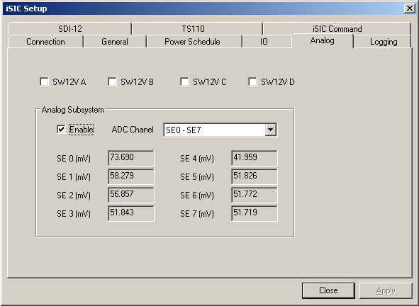
12. Click on the Analog tab.
13. Check the “Enable” box under Analog Subsystem.

Figure 2: Analog tab
14. Place the probe in a known zero solution. Follow the instructions in Turner’s Cyclops-7 manual for proper calibration practices.
15. Record the mV reading from the Analog tab in iChart which corresponds to the analog port to which the sensor is connected.
Note: AD0, AD1, AD2,… on the iSIC Analog terminal strip correspond to SE 0, SE 1, SE 2,… respectively.
Note: The mV reading will not be stable. Record an approximate average value.
16. Place the probe in another known solution (not zero).
17. Record the mV reading.
18. Close the iSIC Setup window.
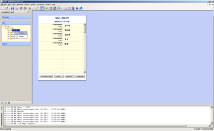
19. Right click on the CYCLOPS-7 sensor in the Site section of the Navigation Panel and select Property.

Figure 3: Opening the “Properties” window
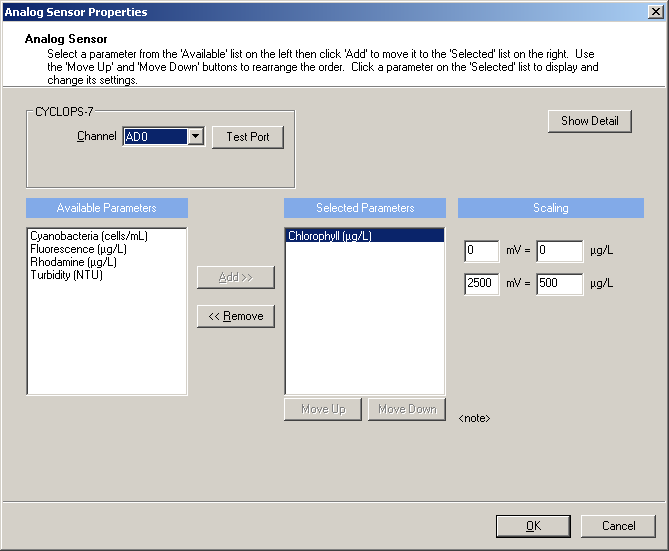
20. Enter the mV reading obtained from the zero solution in the first box of the top row under Scaling.

Figure 4: Properties Window
21. Enter 0 in the second box of the top row.
22. Enter the mV reading obtained from the second known solution in the first box of the second row.
23. Enter the concentration, in ug/L, of the known solution in the second box of the second row.
24. Select OK.
25. Select OK in the dialog box that appears.

Figure 5: Warning dialog
26. Repeat steps 5-24 for any additional sensors.
27. Go to Project | Setup Device Wizard.
28. Click Next until step 6 is reached.
29. Select the iSIC which the device is connected to.
30. Click Program iSIC.
31. Select Yes in the dialog box that appears

Figure 6: Confirmation to reprogram
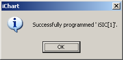
32. Wait for the iSIC to program, then select OK.

Figure 7: Programming succeeded
REV: 13G18
