
NexSens SDL500I and 6100-iSIC Iridium satellite data loggers can be programmed so that only certain data points are transmitted. This may be used in situations where the power draw of the modem needs to be limited or if the satellite transmission is being used only to periodically confirm that the system is functioning properly.
1. For an SDL500I, remove the satellite antenna and use a USB-UW-485P cable to connect to the data logger. Depending on the firmware version, the process detailed at the following link may be necessary to establish connection:
For a 6100-iSIC data logger, remove the modem cable from the DB9 port inside the enclosure and connect a serial cable to PC.
2. In iChart, open the Diagnostic Window by clicking View | Diagnostic Window. This will help determine if communication is successful when working with the SDL500I or 6100-iSIC (ACK = success, Retry! = fail).

Figure 1: Diagnostic Output Window
3. Go to Advanced | iSIC | iSIC and confirm the connection settings (PC COM port, Direct connect, etc). Click Connect.
Note: clicking Connect opens a connection to the COM port that the USB cable is using and does not refer to whether or not the PC is connected to the SDL500I or 6100-iSIC.
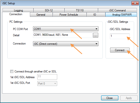
Figure 2: iSIC Setup Menu
4. Click the General tab to attempt connection to the SDL500I or 6100-iSIC. Confirm connection to the data logger by checking for ACK responses in the Diagnostic Window and for information in the Status group box. Confirm that the firmware version is V7.16.17 or later. If it is not, the firmware must be updated:
https://www.nexsens.com/knowledge-base/software/ichart/isicsdl500-code-updates-in-ichart.htm

Figure 3: Verify Firmware Version
5. Click the Power Schedule tab. Select Fix option, check one Time box and enter 12:00:00 AM and a Duration of 1 min. These settings turn the satellite modem off at all times except when it is programmed to transmit a message (in Step 7).

Figure 4: Set Power Schedule
6. Click Apply to submit the changes. Confirm that changes are accepted through ACK responses in the Diagnostic Window and with the on-screen message that appears.

Figure 5: Confirm Power Schedule Settings
7. Click the IO tab. Enter the desired values for the Iridium Transmit Interval and the Iridium Transmit Offset.
The Iridium Transmit Interval refers to how often the data logger will send a reading. In the example shown in Figure 6 below, a 720 minute interval is used to send data points twice per day (every 12 hours).
The Iridium Transmit Offset refers to how often the data logger will wait to send a reading at each transmit interval. In the example, a 120 minute offset is used so that the data logger will wait 2 hours before sending data.
The result of the 720 minute transmit/120 minute offset is that the data logger sends 2 data points each day: 1 at 2:00 AM and 1 at 2:00 PM.

Figure 6: Set Iridium Transmit Intervals
8. Click Apply to submit the changes. Since an on-screen message does not appear, check for ACK responses in the Diagnostic Window. Then, close the Advanced | iSIC | iSIC menu, reopen it and reconnect to the General, Power Schedule and IO tabs to confirm the correct settings.
SDL500 configuration is now complete.
Downloading ALL Data Via Direct Cable Connection
Due to the structure of the iChart database, if the above process is used to transmit only select data points, it will be necessary to create a duplicate iChart database in order to download all data points from the SDL500I or 6100-iSIC data logger.
9. Before visiting the site, create a duplicate iChart project file (.icr file) to use for downloading the entire data set. To accomplish this, go to Help | Open Users Folder and locate the ProjectName.icr file. Make a copy of this with a new name (e.g. ProjectName2.icr).
10. Open this .icr file in iChart. In the Navigation Panel, right click on SDL500I or 6100-iSIC and select Property.

Figure 7: iChart Navigation Panel
11. In the window that appears, select Direct to PC from the Connect Through drop-down list and select the COM port the UW-USB-485P or serial cable is using from the PC COM Port drop-down list.

Figure 8: Set Connection to Direct
12. When at the field site, open iChart with this .icr project file.
13. Connect to the data logger as done in Step 1.
14. Click the Interrogate button, and the data will begin downloading. Verify this by looking for ACK responses in the Diagnostic Window and by looking at the information in the status box that appears (the date of data being downloaded is shown).
Note: The data download may take up to 2 hours to complete, depending on how much data is stored. It is possible to increase the interrogation speed by following the instructions at the link below, but the settings must be changed back to the original settings after the interrogation is complete, otherwise satellite communications will not work:
15. When interrogation is completed, all data is stored in the database specific to the duplicate .icr file.
Rev: 14 C14