
A characteristic inherent to all SDI-12 devices is that each has an internal SDI-12 address. The SDI-12 address is used as a reference for issuing commands from a master device such as a NexSens iSIC or SDL500 data logger. Thus, each SDI-12 device that is connected must have a unique address.
The address setting can be verified or changed by issuing SDI-12 commands through iChart. In some cases, it may be necessary to change the address to match the iChart configuration or to interface multiple SDI-12 sensors to an iSIC or SDL500.
Verify/Change an SDI-12 Address
1. Remove all SDI-12 devices from the iSIC or SDL500 data logger except for the SDI-12 sensor that will be checked. This is to avoid accidentally changing settings on the wrong SDI-12 sensor or possibly changing a sensor to an SDI-12 address that is already being used by another sensor.
2. In iChart, navigate to Advanced | iSIC | iSIC. The iSIC Setup menu will open:
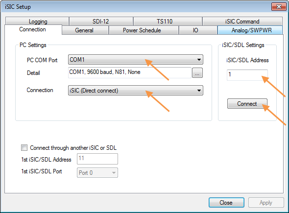
Figure 1: iSIC Setup Menu
3. Enter the appropriate communication settings for the data logger (e.g. COM port, IP address, etc). Confirm the COM Port if applicable and enter the iSIC/SDL address. If unknown, the address may be left at zero for direct connect or cellular systems. For radio systems, the correct address must be entered.
4. Click Connect.
5. When “Connect” changes to “Disconnect”, click the General tab to read the configuration of the iSIC or SDL500. Confirm that there is valid information in the Status group box of the General tab (iSIC Time, Main Battery, RTC Battery, Firmware version, etc.). If “???” can be seen in some areas, double check the communication settings in the Connection tab and reattempt connection.

Figure 2: Verify Successful Connection
6. Once connection is confirmed, click on the SDI-12 tab. This allows SDI-12 commands to be manually sent to the sensor.
7. To verify the current address, remove all other SDI-12 sensors from the logger and enter “?!” into the Command line and press Send. A response should be given in the format:
ACK:
a<CR><LF>
where a is the SDI-12 address of the device. Make note of this address.
NOTE: ?! is a universal command that all SDI-12 sensors will respond to regardless of address. Therefore, this command should only be sent when there is a single SDI-12 sensor attached to the iSIC data logger.

Figure 3: SDI-12 Response from Address 0
8. The address can be changed using the SDI-12 Change Address (A) command. Enter “aAb!” into the Command line (where a is the current SDI-12 address and b is the desired new address) and click Send. A response should come from the SDI-12 sensor in the format:
ACK
b<CR><LF>
Note: Do NOT set a non-numerical SDI-12 address. Although SDI-12 protocol permits non-numerical addresses, these cannot be read by iSIC or SDL500 data loggers. Use a numerical value 0-9, and tag the sensor with the new address so that it can be easily identified.
An example of a sensor SDI-12 address change from 0 to 1 is shown in Figure 4:

Figure 4: SDI-12 Address Change from 0 to 1
9. Repeat steps 1-8 for additional sensors if necessary.
Update iChart Configuration
After changing the SDI-12 address of a sensor, the new address can be specified in the Smart Sensor Properties menu when the device is added in the iChart Setup Device Wizard. If the device has already been added, the settings can be updated:
10. Locate the sensor in the iChart Navigation Panel. Right-click and select Property.

Figure 5: iChart Navigation Panel
12. In the Smart Sensor Properties menu, check the address listed in the SDI-12 Address field and update if necessary. Click OK if a change is made. Otherwise, click Cancel.
Also verify that the Selected Parameters list matches the EXACT order AND units of the sensor output. The parameters will be misaligned in iChart if they are not ordered correctly for each SDI-12 device.

Figure 6: Smart Sensor Properties Menu
13. If changes are made in the Smart Sensor Properties menu, the data logger must be reprogrammed through the Setup Device Wizard for the changes to take effect.
Note: Reprogramming a data logger formats the memory and erases all stored data. Be sure to interrogate the data logger to acquire all data prior to making any changes and reprogramming the logger. Alternatively, the SDI-12 address of the sensor can be changed to match the existing configuration by following Steps 1-8.
REV: 14A28