The iSIC data logger can be configured to output data to a GOES-compatible transmission system such as the Stevens Water SatComm. In addition to configuring the iSIC, a GOES account must also be registered with NOAA / NESDIS. The steps for configuring the GOES output are as follows:
1. If creating a new iChart .icr project file, go to File | New Project and give the file a name. If modifying an existing project file, go to Project | Setup Device Wizard.
2. Reference the Setup Device Wizard guide for instructions on adding sites, data loggers and sensors to the iChart project file:
http://www.nexsens.com/knowledge-base/software/ichart/ichart-setup-device-wizard.htm
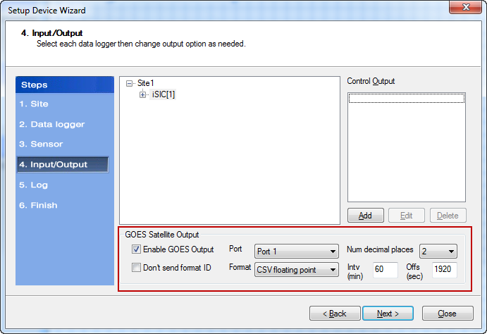
3. At Step 4: Input/Output, enable GOES Satellite Output by placing a check in the Enable GOES Output box.
4. Configure the serial connection settings between the iSIC and the GOES transmission device. The options are:
- Send/don’t send format ID – Determines whether the data format ID will be sent with each data record.
- 0 = CSV floating point
- 1 = CSV fixed point
- Port – Select the serial port on the iSIC to which the GOES transmission device is connected (e.g. P1.Rx & P1.Tx [Pins 5 & 6] on the iSIC Digital terminal is Port 1).
- Format – Choose either CSV floating point or CSV fixed point depending on how the data will be parsed.
- Num decimal places – Select how many decimals will be logged for each parameter.
- This settings applies to all parameters being logged by the iSIC (Due to limited memory)
- Floating: Dictates the maximum number of decimal places allowed
- Fixed: Specifies the power of 10n that the reported number should be divided by to determine the actual value
- Ex. If the logger is setup for fixed point with 2 decimal places and 5026 is transmitted, the actual logged value is 5026/102 = 50.26
- Intv (min) – The PERIOD in MINUTES assigned by NOAA for your transmission window (Needed to determine proper time to send data from the iSIC to the SatComm transmitted)
- Offs (sec) – The FIRST value in SECONDS assigned by NOAA for your transmission window (Needed to determine proper time to send data from the iSIC to the SatComm transmitted)
Figure 2 shows an example of GOES data messages with CSV floating point output and 0 decimal places.
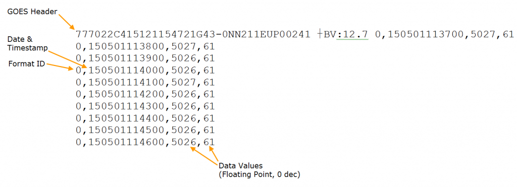
Figure 2: Sample GOES Data
5. The iSIC can also be configured to send alarm messages. If an alarm is triggered, the GOES transmission device will attempt to send the flagged data immediately rather than waiting for the next scheduled interval. Click the Add button to begin configuring the alarm.
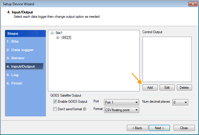
Figure 3: Add Alarm
6. Check the Enable iSIC Output Control box and give the alarm a name. Click the Add button.
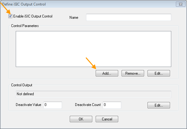
Figure 4: Enable iSIC Control Output
7. Fill in the following fields:
- Parameter – Select the parameter that will be used to trigger the alarm.
- Condition – Choose from less than or equal (<=) or greater than or equal (>=).
- Value – Set the threshold value at which the alarm will trigger.
- Count – Choose the number of consecutive times that the threshold value must be exceeded before the alarm will trigger.
Click OK when finished.
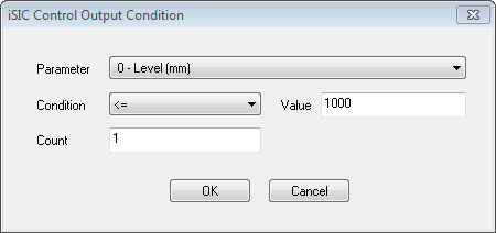
Figure 5: Set Alarm Conditions
8. The alarm will now appear in the Control Parameters box. To set the alarm action, click the Edit button at the bottom right.
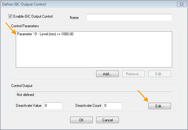
Figure 6: Add Alarm Action
9. From the drop-down list, select Send msg to GOES modem. Then, click OK.

Figure 7: Set Alarm Action
10. Enter values in the Deactivate Value and Deactivate Count fields. This determines when the alarm will reset so that it can be triggered again. Review all settings, then click OK when finished.
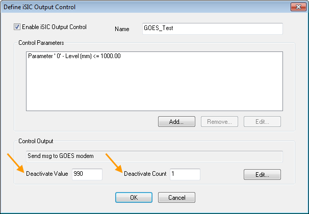
Figure 8: Configure Deactivation Settings
11. The newly configured alarm will appear in the Control Output section of the Setup Device Wizard. Click the Edit or Delete buttons to change or remove the alarm.
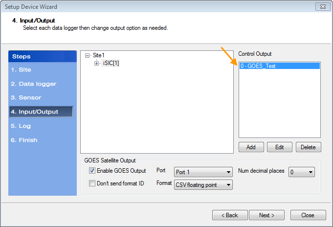
Figure 9: Alarm List
12. When the alarm is triggered, the Format (see Step 4) will automatically change from a numerical value to an asterisk (*) as shown in Figure 10.

Figure 10: Example Alarm Data Message
REV: 15E08

