
To program a 6100-iSIC or SDL500I, it’s necessary to connect to the unit directly. The 6100-iSIC will be connected to using a serial cable (RS-232) and the SDL500I will be connected to using a NexSens UW-Plug to USB adapter.
Programming a 6100-iSIC
Disconnect the satellite modem cable connecting to the iSIC’s DB9 port. Connect a serial cable to the iSIC’s DB9 port directly as shown in Figure 1. One end will connect to the iSIC’s DB9 port and the other will connect to a port on the computer.

Figure 1: Connect to the iSIC with a serial cable. Note that the iSIC-OEM logger is pictured. The logger being connected to may appear different internally.
Next click File | New Project. The Setup Device Wizard will appear. Proceed through the setup as shown in the iChart Setup Device Wizard . However (in Step 2 – Data Logger), when adding “6100-iSIC”, change the connection type to “Direct to PC” in the iSIC Data Logger Communication Properties window. In this window, confirm the iSIC address and PC COM Port being used.

Figure 2: Change to “Direct to PC” and confirm iSIC address and COM Port
Click OK in this window and proceed through the Setup Device Wizard as needed. This includes adding sensors (with their settings), log and sample intervals and other options. In Step 6, highlight the 6100-iSIC to be programmed, click Program iSIC and then click Finish after programming is successful.
In the new iChart project that opens following programming, go to the Navigation Panel. Right-click the 6100-iSIC and select Property.

Figure 3: Right-click 6100-iSIC
Change to “Internet” for the connection. Check the iSIC address and enter the IMEI address for the 6100-iSIC. This number will be provided by NexSens. Click OK.

Figure 4: Change to “Internet” and enter NexSens-provided IMEI number
The 6100-iSIC has been successfully programmed.
Programming an SDL500I
The process for programming an SDL500I is mostly the same, with a few exceptions. A UW-Plug to USB cable will be used. Since the satellite modem on an SDL500I can’t be disconnected from the 232 channel, only a cable communicating through RS-485 may be used.

Figure 5: UW-Plug to USB cable
The plug end of the cable will connect to the top port of the SDL500 and the USB end will connect to a USB port on the iChart computer. Using an RS-485 UW to USB cable (Part# UW-USB-485P) to program an SDL500I:
- Open iChart. Next, select Advanced | Terminal. Connect the USB end of the UW to USB cable being used to a COM port on the computer. Select that COM port (check the Port on the Device Manager by clicking Start | Right-click Computer | Manage. Unplug the connecting cable, then reconnect it to see which port disconnects and reconnects.) in the dialog box and “Direct connect” as the connection type. Click Connect and a white window should appear.
- With batteries in the SDL500, unscrew the white battery lid. Lift it up so that the lid doesn’t contact the batteries. Wait about 10 seconds – then screw the lid back on while connecting the UW-plug end of the cable at the same time.
- When a message appears in the terminal (like “SDL500I” or “NexSens iSIC”), type “esc-4-8-5”.
- Look for a message that ends with %485. If one doesn’t appear, re-cycle power and repeat.
- Once %485 is the last line in the terminal, close the terminal.
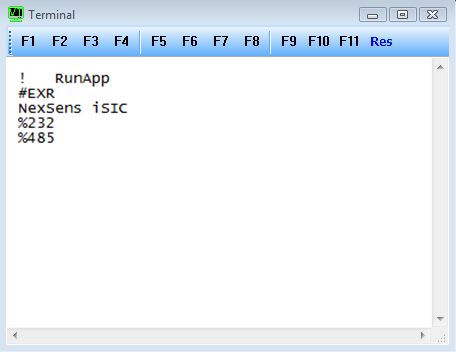
Figure 6: “%485” using last line in Terminal. “NexSens iSIC” is shown as an example.
After closing the terminal, click File | New Project. Follow the steps above for programming a 6100-iSIC or refer to the guide on the Setup Device Wizard for more information.
REV: 13H16