To access the 5100-iSIC from the internet, its address must be opened to the public. This typically is done with port forward on the router.
5100-iSIC Setup
——————–
IP: internal_IP
Port: 9999 and 10001
Router Setup
——————–
IP: public_IP
Port: 9999 and 10001
The public_IP is the IP address of the router that the public can access.
The router should be set to open a pinhole (or port forwarding) to map the public_IP:9999 and public_IP:10001 to internal_IP ports 9999 and 10001.
To access the 5100-iSIC from the internet, specify public_IP in your Port Redirector setup.
The router must have a static IP address. This is so that the IP address entered into the Port Redirector software does not need to change each time power is cycled to the router.
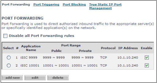
Figure 1: Example Comcast router port forwarding setup
Installing Software
1. Insert the CD that came with the 5100-iSIC device. The installation screen should automatically be displayed. Click Software.
Note: The software may also be downloaded from the Downloads page on this web site.
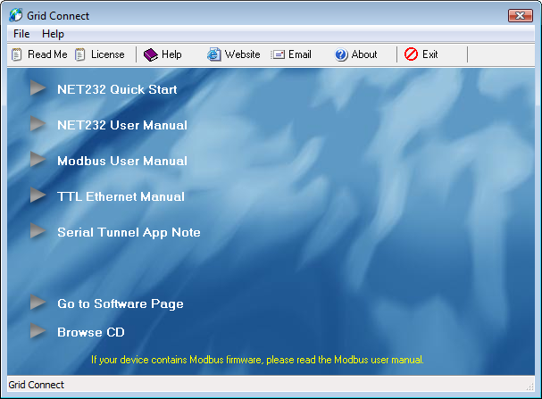
Figure 2: Grid Connect Software Installation Prompt
2. Next click on Go to Software Page.

Figure 3: Grid Connect Software Page
3. Click .NET Framework Install and follow the installation wizard. This is required for the software to work correctly.
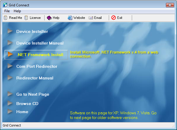
Figure 4: Install .NET Framework
4. After successfully installing the .NET Framework, click on Device Installer and follow the installation wizard. This will allow for setup of a specific IP address if needed.
5. After successfully installing the Device Installer, click Com Port Redirector (This will install CPR Manager and CPR Monitor) and follow the installation wizard. This will allow for accessing the 5100-iSIC through a virtual COM port.
On the local network the device is installed on…
Note: this step must be performed on the local network the 5100-iSIC is connected to. For example, the computer should be connected to the same switch or router the 5100-iSIC is connected to.
6. Run the DeviceInstaller from the Start Menu. Click Search to find devices.
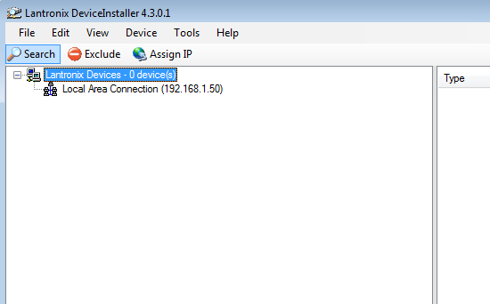
Figure 5: DeviceInstaller
If a static IP address is automatically assigned, proceed to Step 7. Otherwise, if it is necessary to assign a static IP address, highlight the device and click the Assign IP icon. Enter the hardware address of the device and click Next.
Note: the address assigned here should be based on the individual network. Contact the system administrator for allowable IP addresses.
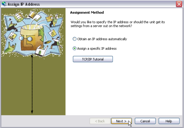
Figure 6: Assign a specific IP Address
Place a check in “Assign a specific IP address” and click Next. Then enter the desired IP address (make sure it will not conflict with the DHCP server).
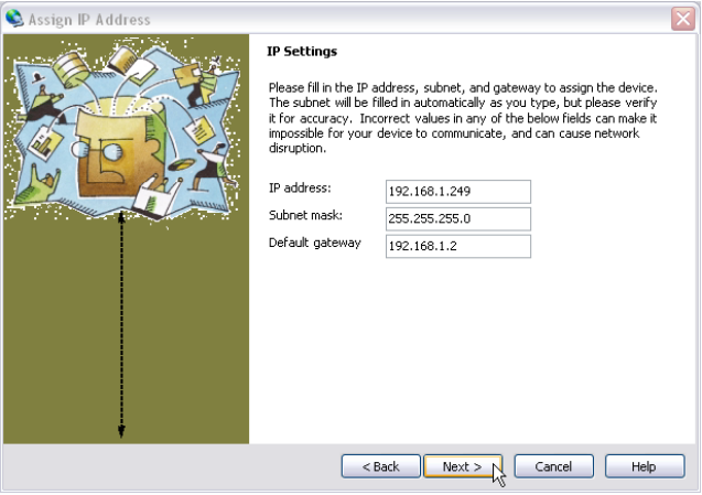
Figure 7: Enter specific IP settings
If the device will be running on the same subnet as the iChart computer, run the command prompt and enter “ipconfig” to access the Subnet Mask and Default Gateway. Otherwise contact a system administrator for these values.
- To access the command prompt from the Start Menu select: Start -> All Programs -> Accessories -> Command Prompt. At the prompt, type “ipconfig” and hit Enter.
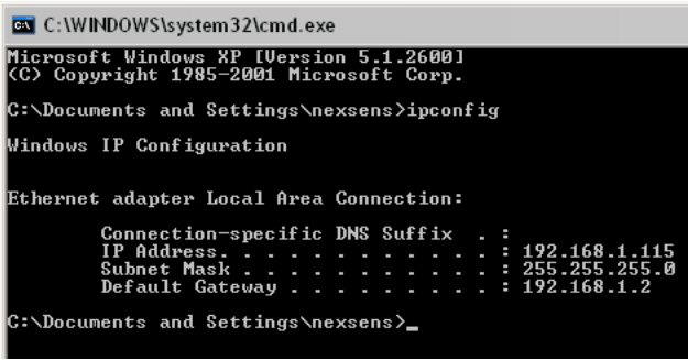
Figure 8: ipconfig in a Command Prompt
Click the Assign button when ready. Make sure the device is still powered and connected to the internet.
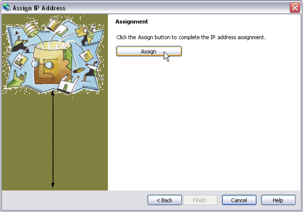
Figure 9: Click the Assign button
After successfully assigning an IP, record the IP Address shown as it will be needed later. After the IP has been assigned, cycle the power to the 5100-iSIC.
7. In the Lantronix Device Installer, click the Tools menu and select Ping.

Figure 10: DeviceInstaller
The Ping Device window will appear. Enter the IP Address of the 5100-iSIC device that was found during search and click Ping. “Reply from…” should appear. This means the data logger is working.

Figure 11: DeviceInstaller
If required, configure any router to port forward an external IP address to the internal 5100-iSIC IP address, so that computers offsite may access it. Port 10001 for TCP/IP traffic and port 9999 for telnet traffic must be open for the device to work properly.
On the computer running iChart software…
After successfully pinging the device locally, close DeviceInstaller software and run CPR Manager from the Start menu on the computer that will be running iChart software.
8. Open the CPR Manager software. Click Search For Devices.

Figure 12: CPR Manager
The 5100-iSIC should appear as a device in the Device List.

Figure 13: Device List in CPR
9. Click the Com Port that will be used. Note that the port must be accessible.
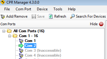
Figure 14: Select Com Port in CPR
If a Com Port is not accessible, click Add/Remove to add one. Select a Com Port in the Com Ports window and click OK.
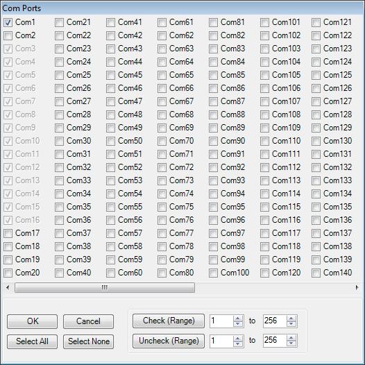
Figure 15: Com Ports Window
10. Refer to the Settings tab to the right.
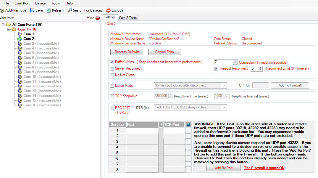
Figure 16: Settings Tab CPR
11. Right-click the 5100-iSIC in the Device List and select “Add to Settings”.

Figure 17: Device List
12. The device Host and TCP Port information will appear in the Settings tab.
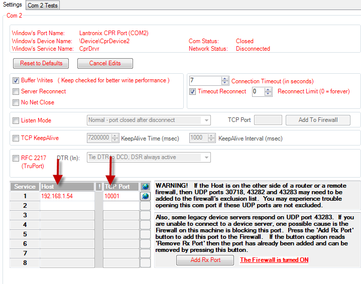
Figure 18: Settings Tab
Click Save at the top to save the settings. Then click Close and run iChart.
13. Select Advanced | iSIC | iSIC from the menu. The iSIC Setup window will appear.
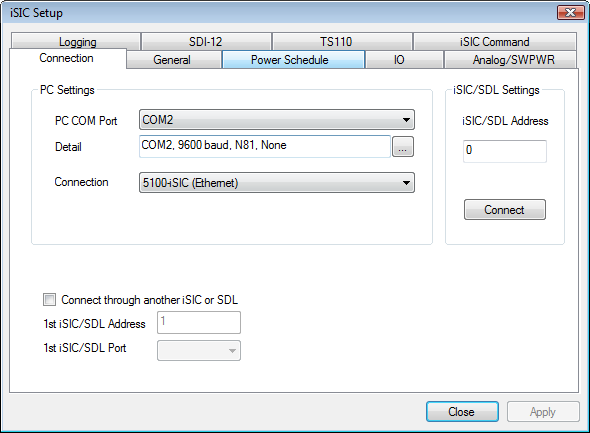
Figure 19: Connection Tab
14. Click on PC COM Port and select the COM port recorded earlier. By default, the iSIC Data Logger will use 9600 baud, N81 (No parity, 8 data bits, 1 stop bit). If there is more than one 5100-iSIC connected to the network, enter the exact address of the logger being connected to. If only one 5100-iSIC is connected, the address can be left as “0”. The Connection type should be set to “5100-iSIC”.
15. Click Connect.
16. Click the General tab. iChart will read the current configuration settings of the iSIC. This will take a few seconds. After iChart has successfully read the status information, it will be displayed on the bottom of the screen. If ‘???’ appear displayed in the iSIC Time or Firmware fields, go back and check the setup.
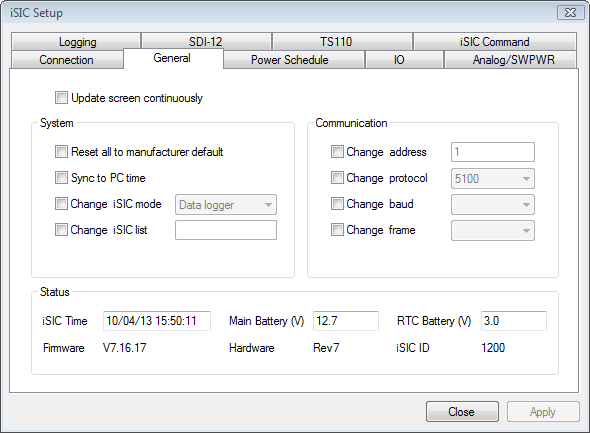
Figure 20: General Tab
Sensors may be wired into the logger using the appropriate Sensor Interface manuals. Use the iChart Setup Device Wizard to setup a project file.
REV: 13K07
