Overview
The NexSens 5100-iSIC (Intelligent Sensor Interface and Control) uses an integrated Ethernet modem to provide a dedicated port for continuous Ethernet-to-router communication.
What’s Included
- Data logger with Ethernet modem
- 12 VDC battery
- iSIC Kit
- (2) Gland fittings
- (5) Desiccant packs
- RS-232 interface cable
- (4) 56 Ω resistors
- CAT5E Patch cable
- DB-9 Null modem adapter
- Grid connect driver and utility software CD
Software Installation
1. Install iChart software on a Windows computer using the provided CD-ROM or from the NexSens Downloads page:
http://www.nexsens.com/support/downloads
2. If iChart is installed on a PC with Windows Vista, 7 or 8 OS, setup the software to run with Administrator privileges to allow write access to the Program Files directory:
http://www.nexsens.com/knowledge-base/software/ichart/windows-7-and-windows-vista-os.htm
3. Register the software online when running for the first time:
http://www.nexsens.com/support/register-software
4. On the iChart PC, insert the Grid Connect software CD and click Go to Software Page.
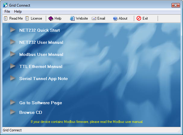
Figure 1: Grid Connect Software Installation Prompt
5. From the Software menu, install the COM Port Redirector (this appears on the computer as CPR Manager after installation).

Figure 2: Grid Connect Software Page
Ethernet Modem Configuration
The CPR Manager is used to assign a virtual COM port to the Ethernet modem, which can be accessed by iChart in order to communicate with the 5100-iSIC data logger. While the Ethernet modem may be assigned an IP address via DHCP, a fixed (static) IP address must be provided so that the COM port settings do not change. Setting a static IP address is done by connecting directly to the Ethernet modem using the instructions provided at this link:
COM Port Configuration
6. Within the iSIC enclosure, connect the DB-9 cable to the connector on the iSIC board.
7. Using the CAT5E Patch Cable, connect the iSIC to the same local network the computer is on.
8. Power the iSIC by connecting the 12 volt battery and/or external power supply. Observe the green blinking LED in the hole at the end of the analog terminal strip. This only blinks for 15-20 seconds during warm-up to confirm that the data logger is powered and ready.
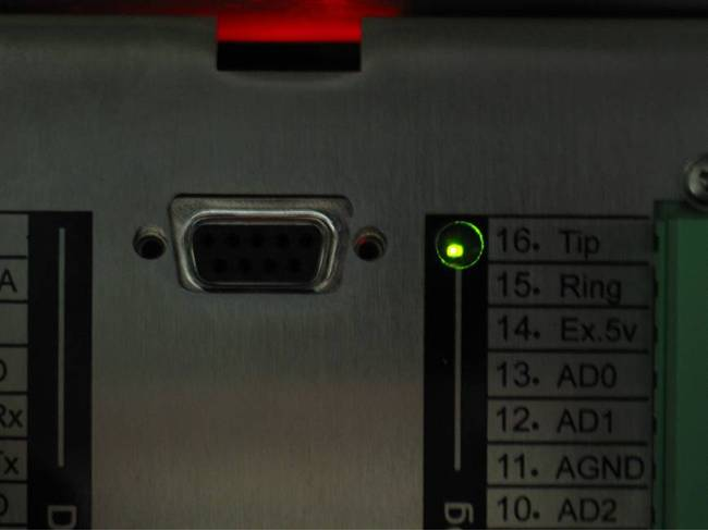
Figure 3: Blinking Green LED Light
9. Open the CPR Manager software. Click Search For Devices.

Figure 4: Search for Devices
The 5100-iSIC should appear as a device in the Device List.

Figure 5: Device List in CPR
10. Click the Com Port that will be used and make note of the port number as this will be needed to setup the connection in iChart. Note that the port must be accessible.
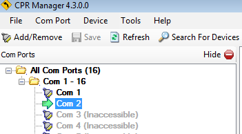
Figure 6: Select Com Port
If a Com Port is not accessible, click Add/Remove to add one. Select a Com Port in the Com Ports window and click OK.
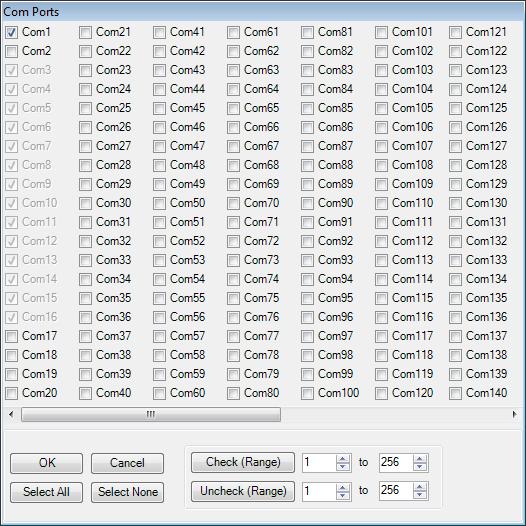
Figure 7: Com Ports Window
11. Refer to the Settings tab to the right.
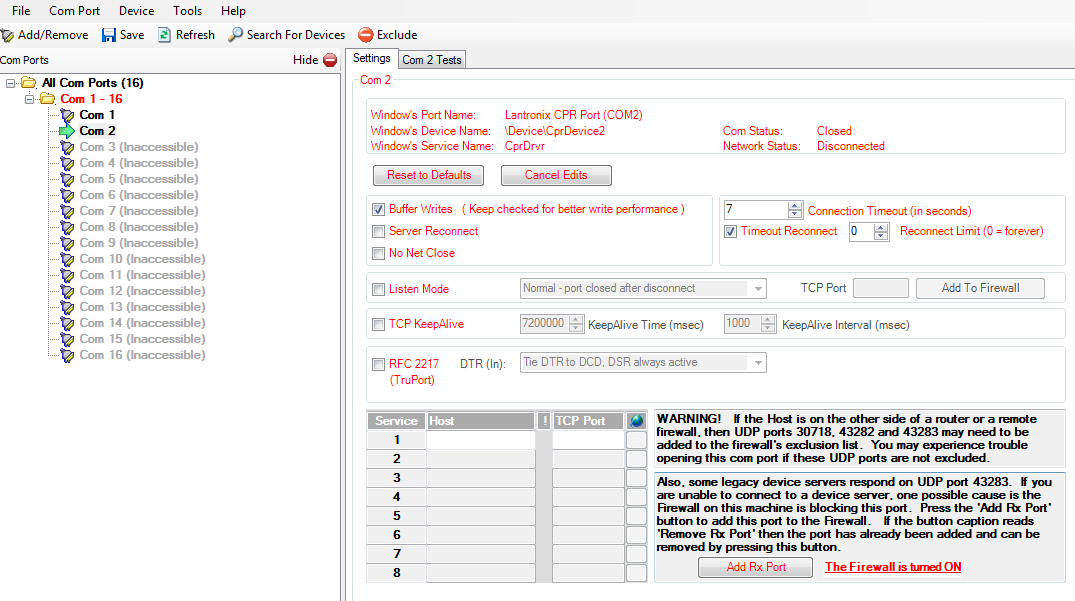
Figure 8: CPR Settings Tab
12. Right-click the 5100-iSIC in the Device List and select Add to Settings.

Figure 9: Device List
The device Host and TCP Port information will appear in the Settings tab. Note that the port forwarding requires that the TCP Ports 10001 and 9999 must not be blocked by a firewall. Additionally, the UDP ports 30718, 43282 and 43283 must be added to the firewall exclusion list if the device will be accessed from outside the LAN (see Warning! note in screen shot below).
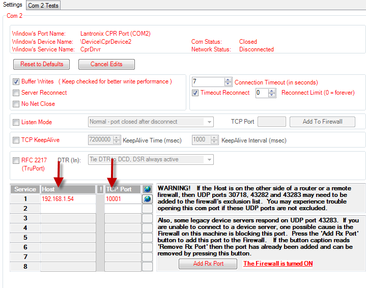
Figure 10: Settings Tab
13. Click Save and then close CPR Manager.
iChart Communication Test
14. Open iChart without a project file and select Advanced | iSIC | iSIC from the menu. The iSIC Setup window will appear.
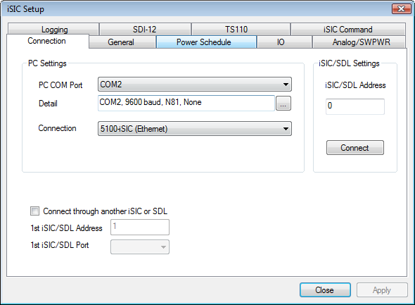
Figure 11: iSIC Setup Window
15. Select the correct COM port (from CRP Manager setup), then select 5100-iSIC from the connection drop-down menu. Enter the 5100-iSIC address if known, or leave at 0 if unknown. Click Connect.
16. When the button changes to Disconnect, click the General tab. Confirm the connection is successful by verifying that valid information displays in the Status group box at the bottom of the window (iSIC time, battery voltage, etc). If ??? is displayed, return to the CPR Manager and/or Connection tab and check the communication settings.
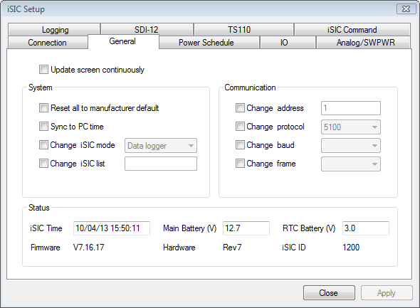
Figure 12: General Tab in iSIC Setup Window
17. After verifying communication, return to the Connection tab, click Disconnect, and close the iSIC Setup window.
Configuring with iChart
18. Refer to the Sensor Interface Guides for connection of sensors.
19. Ensure power is supplied to the data logger.
20. Add the 5100-iSIC to an iChart project file.
- Follow the Setup Device Wizard to add a site name, and then select 5100-iSIC from the list of NexSens data loggers. Enter the correct PC COM Port at the prompt and click Test Connection to check communication. Add sensors in iChart by selecting the manufacturer and model number. Continue the Setup Device Wizard, make sure the 5100-iSIC is selected and click Program iSIC to conclude configuration.
REV: 14J17
