Components
The enclosure that houses the NexSens iSIC Printed Circuit Board (PCB), wiring, and battery is a durable NEMA 4X enclosure. It measures 12” x 8” x 7” (inches) and is constructed of heavy-duty fiberglass.
This enclosure is certified for both indoor and outdoor use. Falling dirt, rain, sleet, snow, windblown dust, splashing water, hose-directed water, and corrosion will not damage the enclosure. In addition, the box will be undamaged by the formation of ice on the enclosure.
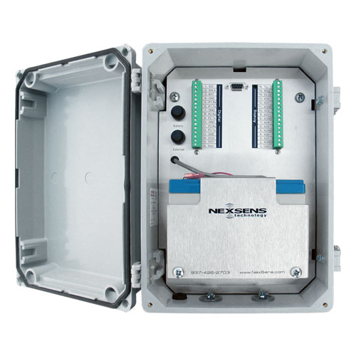
Figure 1: iSIC Enclosure
A number of connectors are located externally on the iSIC enclosure:
(2) Expansion plugs for half-inch conduit or gland fittings
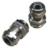
Figure 2: Gland Fittings
Two gland fittings are supplied with each iSIC to allow cables to enter the inside of the iSIC enclosure. Additional gland fittings can be purchased in two packs as part #A75: http://www.fondriest.com/nexsens-a75.htm.
(1) Gortex enclosure vent
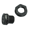
Figure 3: Gortex enclosure vent
A vent made of Gortex material is installed on the outside of the enclosure to allow air to pass and keep moisture out. This keeps the enclosure pressure at equilibrium with the atmosphere.
Spare or additional vents can be purchased as part #A70.
http://www.fondriest.com/nexsens-a70.htm
(1) MS8 connector for the connection of Sensor RS-232 Port 0 or RS-485.
This connector allows for quick connection for instruments such as YSI Sondes, which has a mating MS8 connector at the end of its cable.
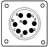
Figure 4: MS8 Connector
(1) Ground lug for electrical grounding
The ground lug on the outside of the enclosure provides an earth ground to the electronics inside as well as any sensors powered by the data logger. A direct burial ground rod version is available as well as a pipe mount grounding clamp.
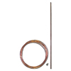
Figure 5: Ground lug for electrical grounding
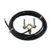
Figure 6: Ground lug for electrical grounding
These grounding kits can be purchased as part #A38 or A38-P.
http://www.fondriest.com/nexsens-ground-kit.htm
http://www.fondriest.com/nexsens-a38-p.htm
More information on why grounding is important can be found here:
http://www.nexsens.com/knowledgebase/grounding.htm
(1) MS2 connector for regulated solar or AC float charger connection
For solar charging applications, three sizes of solar panels are available to keep a NexSens system charging year round. A 20W solar panel is a typical size used as it can keep almost any application charging without worry. An MS2 to flying lead cable can be used to power the data logger from user supplied external power sources.
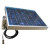
Figure 7: Solar Panel
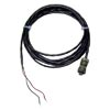
Figure 8: MS2 Connector
Solar panels can be purchased as part #A21 to A23.
http://www.fondriest.com/nexsens-solar-power.htm
http://www.fondriest.com/nexsens-a22.htm
http://www.fondriest.com/nexsens-a23.htm
Contact NexSens to determine the best battery or solar panel size, or find more information regarding the calculations here:
For AC power applications a float charger is used to keep the internal data logger battery fully charged.
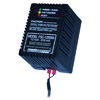
Figure 9: AC Float Charger
If used outdoors, a deep outlet cover is recommended and can be purchased as part #A15.
http://www.fondriest.com/nexsens-a15.htm
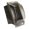
Figure 10: Deep Outlet Cover
Internal
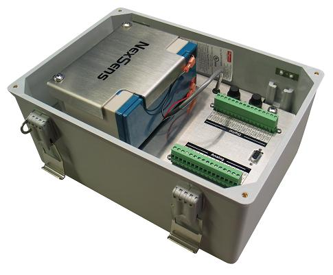
Figure 11: Inside the iSIC enclosure
A number of connectors are located internally on the iSIC enclosure:
▫ Expansion Plugs – A number of connectors are located internally on the iSIC enclosure. These allow an interface to the multitude of sensors in your system. An iSIC data logger allows 4 RS-232 devices, RS-485 devices, 8 analog inputs, a tipping bucket rain gauge, and 10 SDI-12 sensors to be connected at a single time. These numbers can be further increased with expansions. See the following pages for more information.
▫ Internal Battery – The NexSens iSIC comes standard with a sealed rechargeable lead acid 12V 8.5 A-hr battery. Recharging is possible through the use of a float charger or solar panel equipment.
▫ Fuses – Two fuses are located on the left edge of the plate inside the iSIC enclosure. The top fuse connects to the internal battery. The bottom fuse connects to the charger/external power. These are 3A time delay speed type fuses, rated for 250VAC.
Digital and Analog Connectors
Two 16-pin un-pluggable terminal strip connectors are located inside the enclosure. Power and sensors will be connected to these terminals. The connector on the left is for connecting digital and smart sensors. The connector on the right is for connecting analog sensors. Descriptions for the pins on both connectors are given below:
A factory installed option for analog, digital, and galvanic dissolved oxygen sensor expansion is available. The interface connections for expansion are located behind the battery.
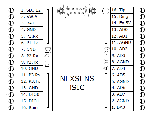
Figure 12: iSIC Digital and Analog Terminal Connections
Digital Connectors
SDI-12: Connection for SDI-12 sensors.
SW.A: 12V, 200 mA power switch.
BAT: Pass-through battery power pin (fused)
GND: Ground (digital)
P1.Rx: RS-232 Receive Pin (Port 1) – Input
P1.Tx: RS-232 Transfer Pin (Port 1) – Output
P2.Rx: RS-232 Receive Pin (Port 2) – Input
P2.Tx: RS-232 Transfer Pin (Port 2) – Output
P3.Rx: RS-485 Receive Pin (Port 3) – Input
P3.Tx: RS-485 Transfer Pin (Port 3) – Output
DIO0: General purpose Digital I/O.
DIO1: General purpose Digital I/O.
Rain: Tipping bucket rain gauge input
Analog Connectors
Tip: Telephone wire connection pin
Ring: Telephone wire connection pin
Ex.5V: 5V Excitation voltage
AD0 – AD7: Analog Inputs
AGND: Analog ground
DA0: Digital to Analog output
REV: 13H02
