
Proteus X-Series Integration Guide
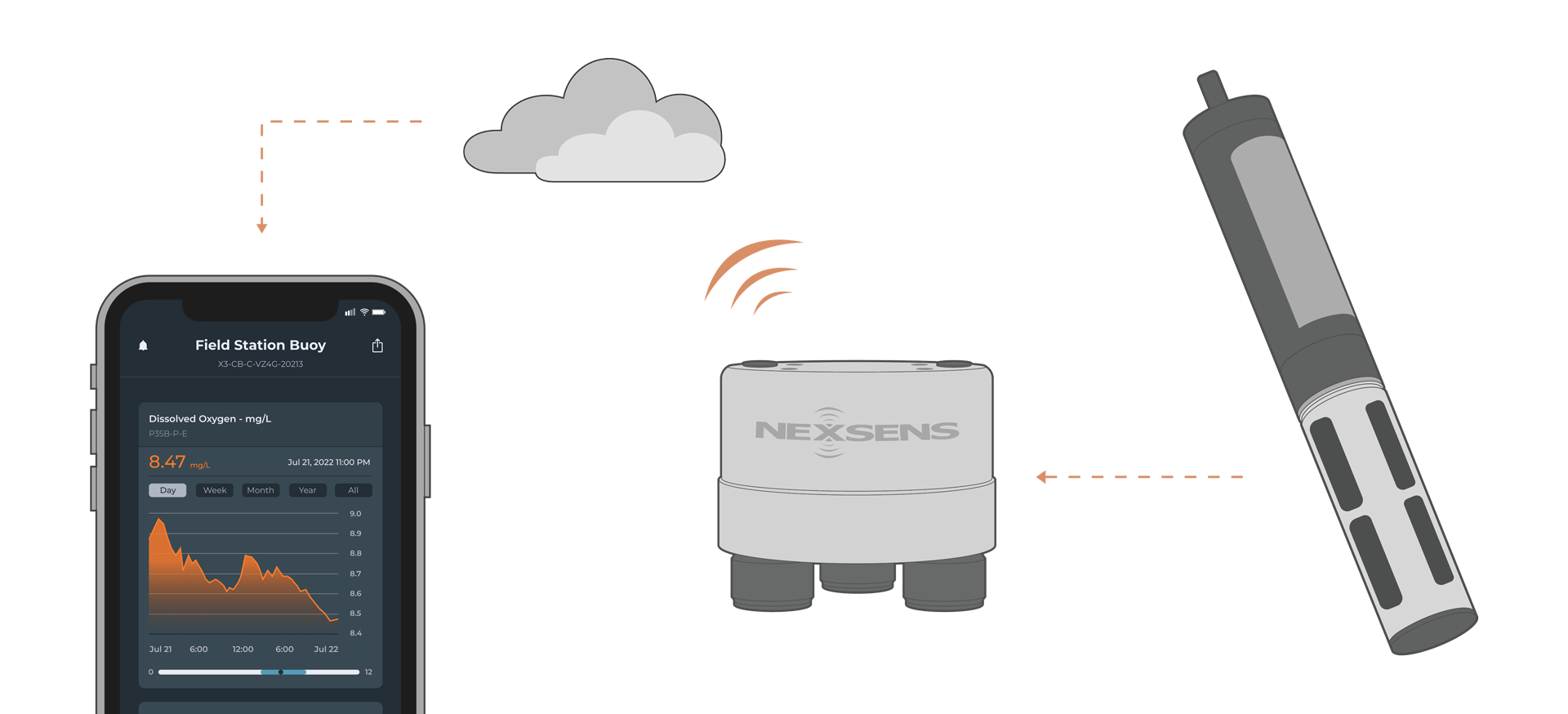
The Proteus Multiparameter Water Quality Sensors are compatible with NexSens X-Series data loggers via the RS-232 sensor interface. Parameter data is transmitted, in real-time, at a user-specified interval (e.g., 10 minutes) to the NexSens WQData LIVE Web Datacenter. There, data is stored on customizable dashboards with statistics and graphical interfaces for each parameter. Users can download and send data reports via Email, FTP, or an API. Below is information on the settings and wiring required to integrate these sensors with a NexSens X-Series data logger.
1. Sensor Integration
- Download the Proteus Manager software and connect to a PC.
- Set the parameter list
- Navigate to Proteus | Sensors and Parameters List
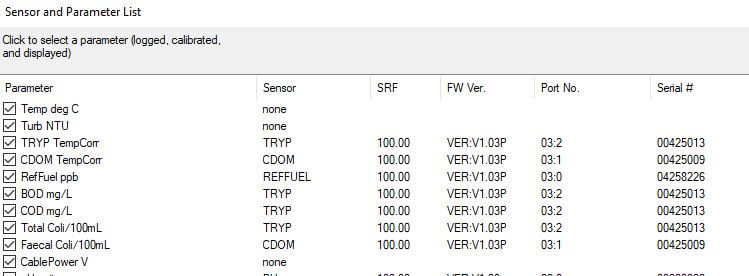
- Select the appropriate parameters and their order.
- Typically, the available parameters are pre-selected before the sonde is shipped from the factory; however, the units for each probe can be set by the user.
- Available parameters will usually have the sensor name, firmware version, port number, serial number, and the Sensor Response Factor.
- After selecting the appropriate parameters, view the live data output to ensure the correct parameters and parameter order are displayed.
- The Date and Time parameter will always be shown and is not within the parameter selection.
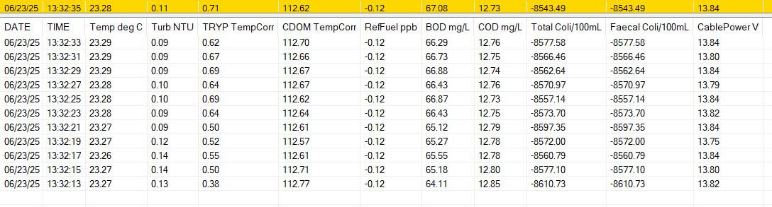
- The Date and Time parameter will always be shown and is not within the parameter selection.
Generic GSI Script Generation
The correct model and parameters must be selected from CONNECT’s sensor library to create a script for the sonde.
- Download the latest version of CONNECT. Connect the logger to a PC and launch CONNECT.
- On the Config tab, click the drop-down arrow to the right of the Create Script button and select Generic GSI
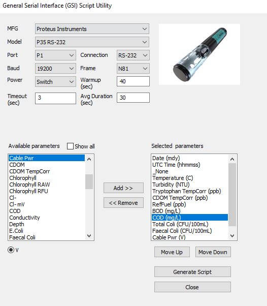
- The Script Utility menu will appear.
- Under Manufacturer, select Proteus Instruments.
- Under Model, select the model you are connecting.
- Port – Select the data logger port that the Proteus will be connected to.
- The P0 port always provides full power.
- Baud – Keep as 19200
- Timeout – Keep as default.
- Connection – Keep as RS-232.
- Frame – Keep as N81.
- Power – Select the power type required for the sensor.
- Switch – Turns on power to the listed sensor port at a specified period of time ahead of each scheduled reading. The sensor powers off once the logger collects data for the reading.
- The Warmup field determines how long the sensor will be powered in advance of each reading.
- Continuous – Power will be applied constantly.
- None – No power is applied to the port.
- Switch – Turns on power to the listed sensor port at a specified period of time ahead of each scheduled reading. The sensor powers off once the logger collects data for the reading.
- Average Duration – The CONNECT script will average measurements over a certain duration of time. Since many sensors communicate through serial communication output at 1Hz, a 10-second average duration would provide an average of 10 overall measurements.
- Available Parameters – Construct the appropriate parameter output list for the sensor by assigning parameters to the Selected Parameters column using the Add, Remove, Move Up, Move Down buttons.
- The total number and ordering of parameters for the script must match the parameter output for the sensor.
- If the sensor outputs a diagnostic or undesirable parameter as a part of its measurement command, it can be omitted from logging. Substitute the _None parameter into its position on the Selected Parameters list.
- Select Generate Script, assign a script number and click OK to save the script in the CONNECT software folder.
- If creating multiple generic scripts for the X3, assign a unique value to each.
- If making modifications to an existing generic script, assign the same script number to overwrite the original.
Automatic Sensor Detection
Once the script is created, transfer and enable it on the data logger.
Before running the sensor detection, ensure all sensors are connected to the data logger and set up correctly by following their integration guide. Sensor detections should only be performed after all sensors are ready for programming.