This article demonstrates how to mount a LI-COR 192 PAR sensor onto a Unistrut arm for small and large instrument cages.
Required Tools
Socket/combination wrench sets: 3/8″, 7/16″, 9/16″
Size 25 metric Allen wrench
Flat head screwdriver
Phillips head screwdriver
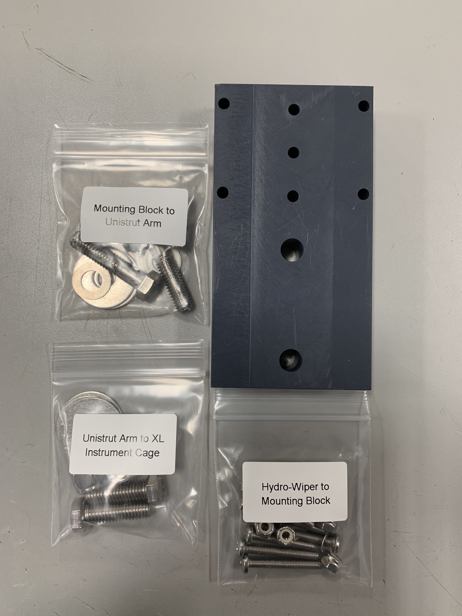
Included Components
- All Cage Sizes
- Mounting Block
- HydroWiper to Mounting Block– (7) 10-32x 1-3/8 pan head bolt, (3) #10 flat washer, (7) 10-32 Nylon insert nut
- Mounting Block to Unistrut Arm– (2) 3/8-16x 1-5/8 hex cap bolt, (2) 3/8 flat washer, (2) 3/8 fender washer
- For Standard Cage Only
- Unistrut Arm to Instrument Cage– (2) 1/4-20x 1″ ID U-bolt, (4) 1/4-20 Nylon insert nut
- For Large Cage Only
- Unistrut Arm to XL Instrument Cage– (2) 3/8-16x 1-1/4″ hex cap bolt, (4) 3/8 fender washer, (2) 3/8-16 Nylon insert locknut

Materials included for PAR installation on small instrument cage
Materials included for PAR installation on XL instrument cage
Attach the Hydro-wiper to the mounting block
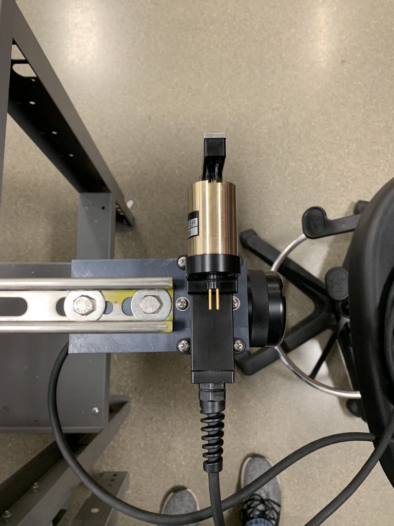
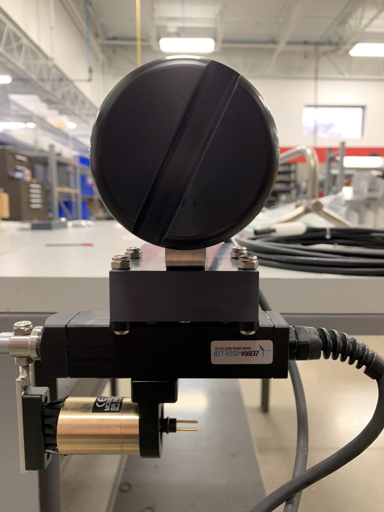
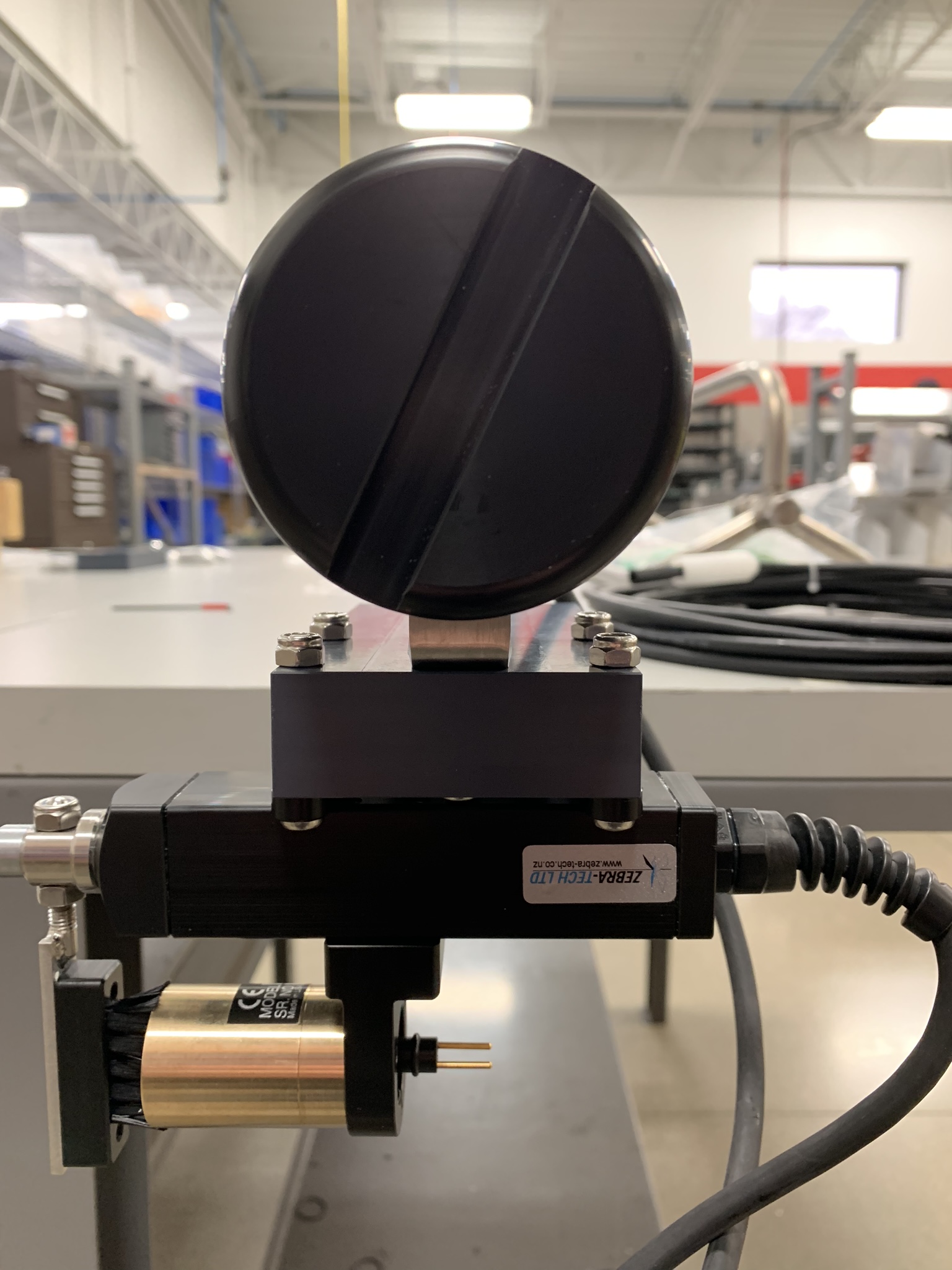
- Use a 3/8″ wrench and a Phillips-head screw driver to attach the Hydro-wiper battery pack to the mounting block with (3) 10-32 X 1-3/8″ pan head screws, (3) #10 flat washers, and (3) 10-32″ nylon insert locknuts from the “Hydro-Wiper to Mounting Block” bag.
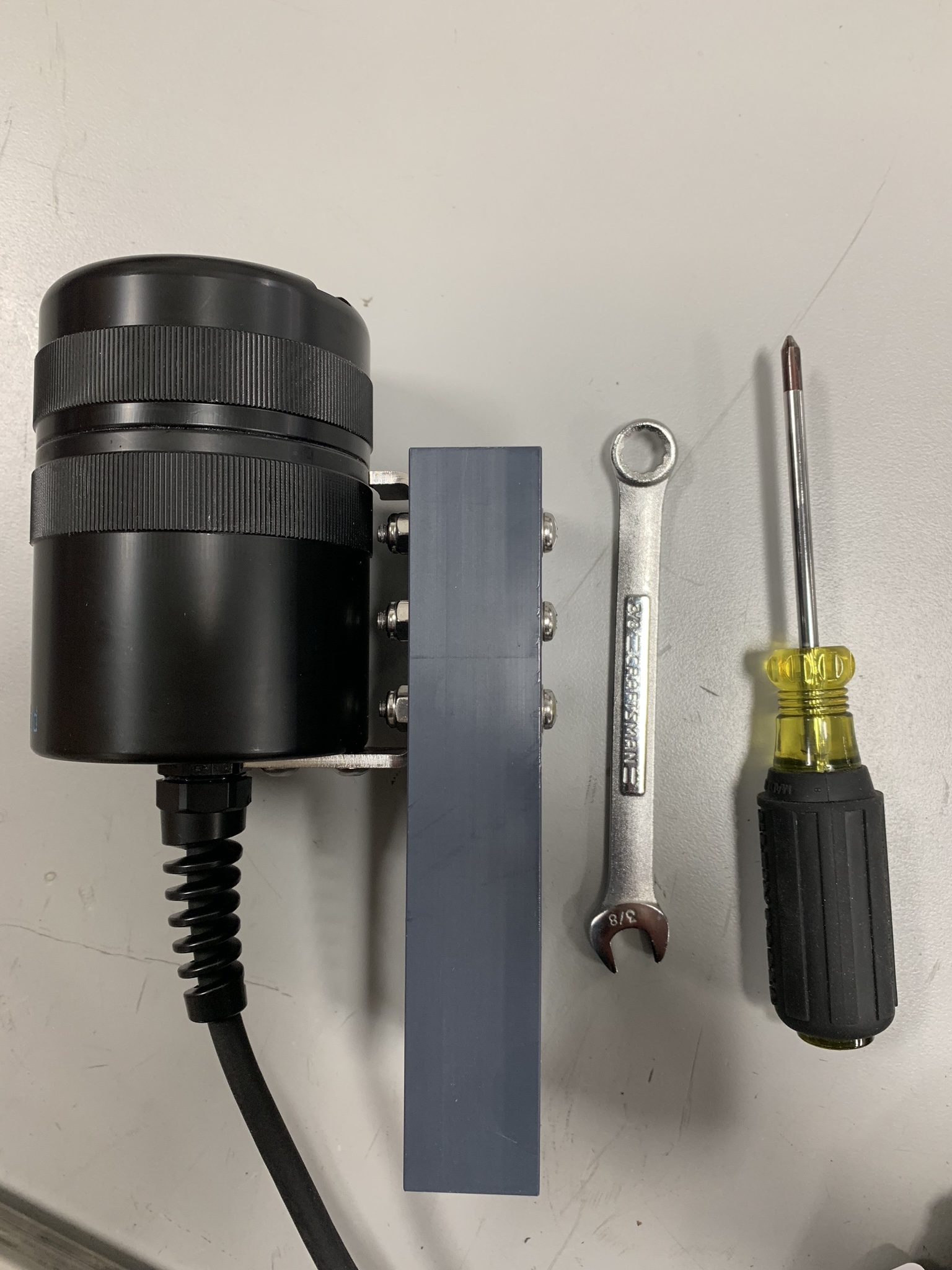
Side view of Hydro-wiper battery pack attached to mounting block
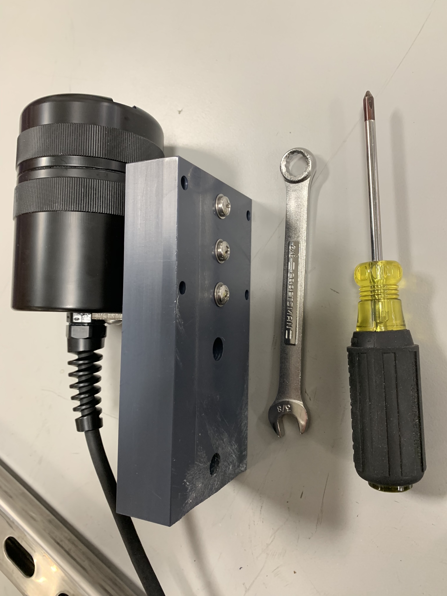
Front view of Hydro-wiper battery pack attached to mounting block
Attach the mounting block to the Unistrut arm
- Use a 9/16″ socket wrench and 9/16″ combination wrench to attach the mounting block to the Unistrut arm using the (2) 3/8-16 X 1-5/8″ hex cap bolts, (2) 3/8″ flat washers, (2) 3/8″ fender washers, and (2) 3/8-16″ nylon insert locknuts found in the “Mounting Block to Unistrut Arm” bag .
- Slide the fender washers into the Unistrut arm and align them with the 2 large holes on the mounting block.

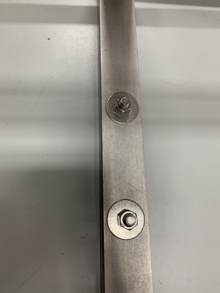
Bottom view of mounting block connected to end of Unistrut arm
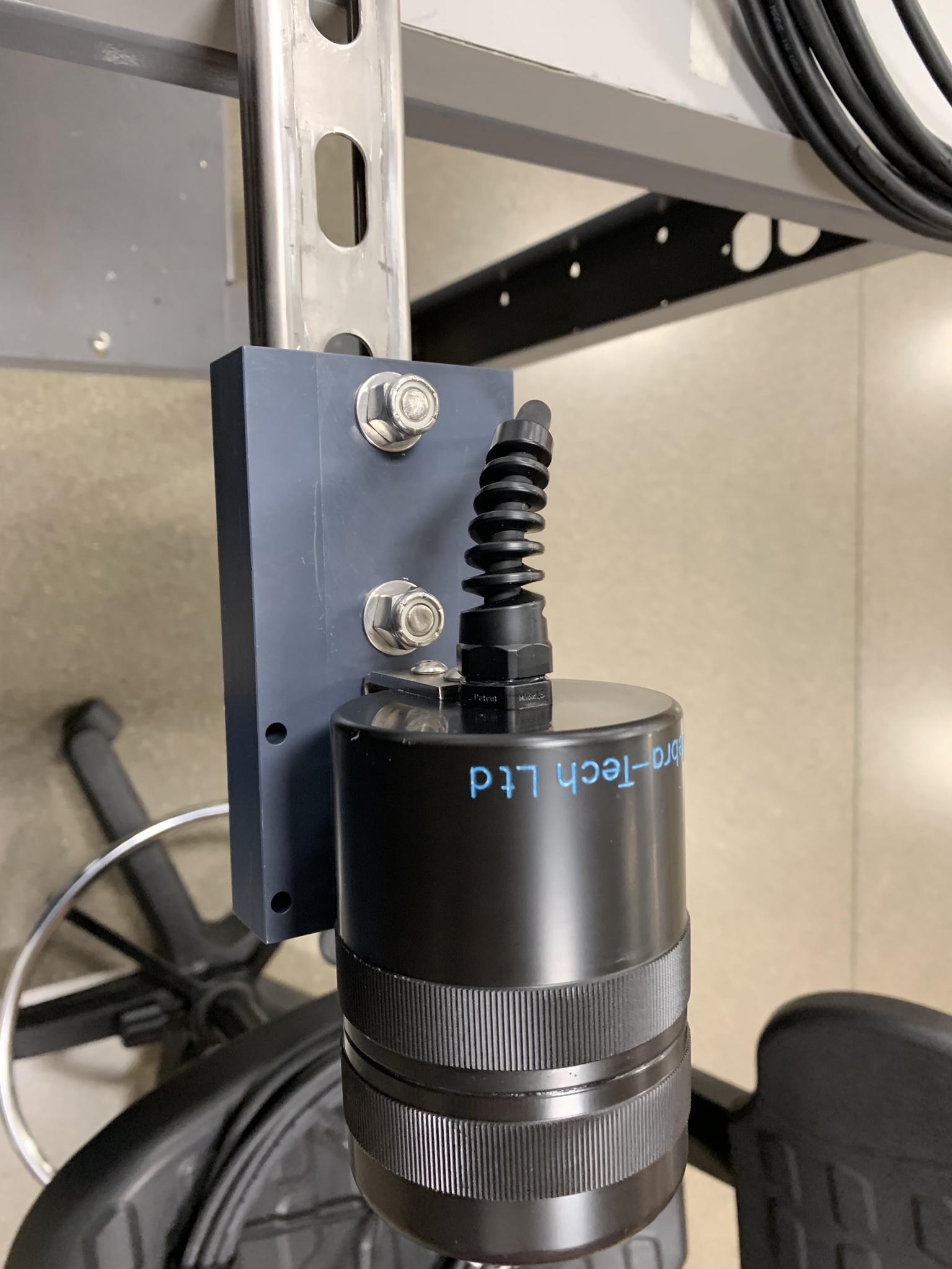
Top view of mounting block connected to end of Unistrut arm
Attach the LI-COR 192 sensor to the Hydro-wiper
1. Use a size 25 metric Allen wrench to remove the sensor holder from the Hydro-wiper.
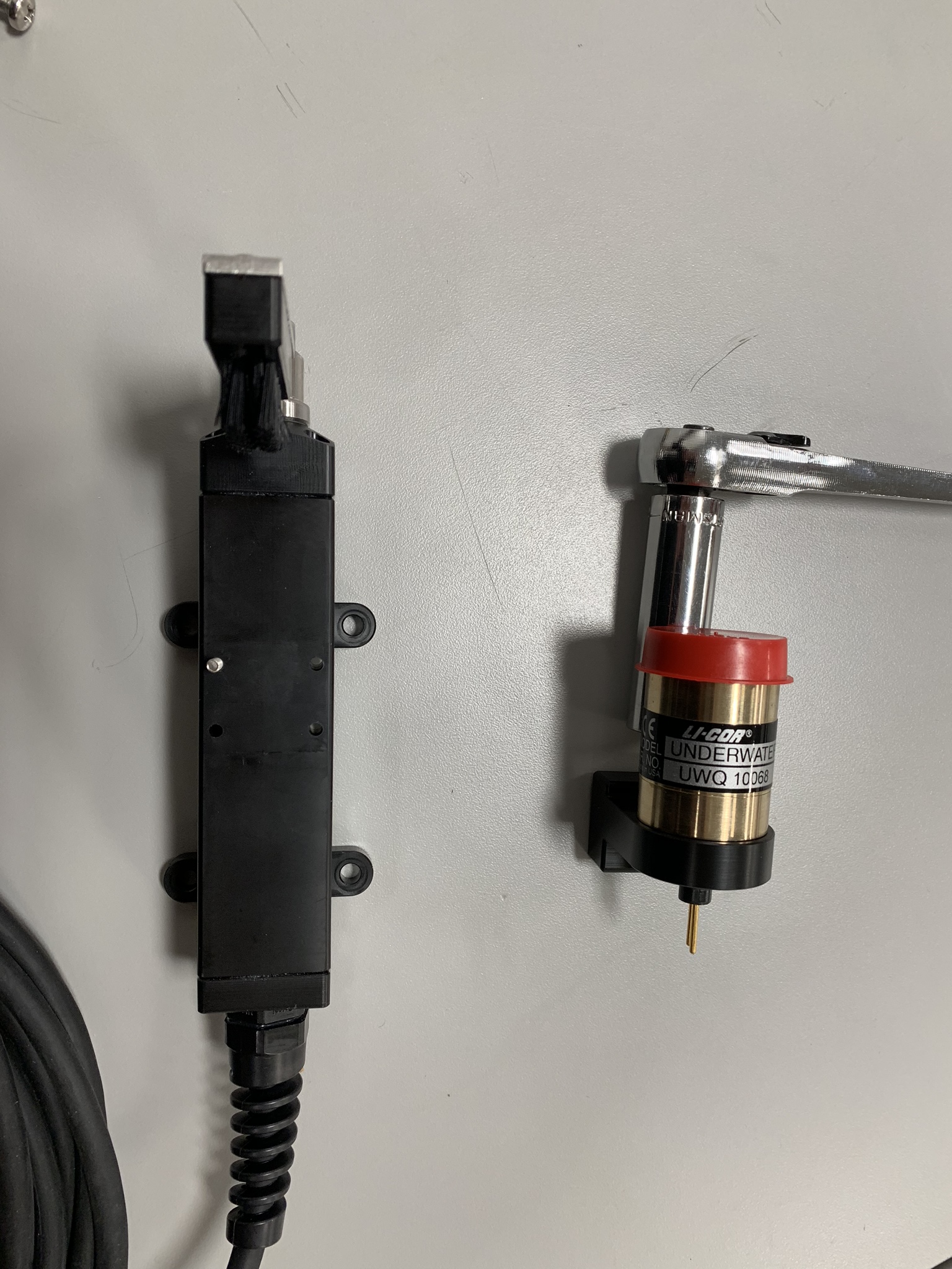
Back view of Hydro-wiper

Front view of Hydro-wiper with sensor holder removed
2. Locate the yellow marking on one of the edges of the Li-192’s black collar. Note this location relative to the sensor label prior to placing it inside the HydroWiper holder. This will be necessary for proper cable orientation later.
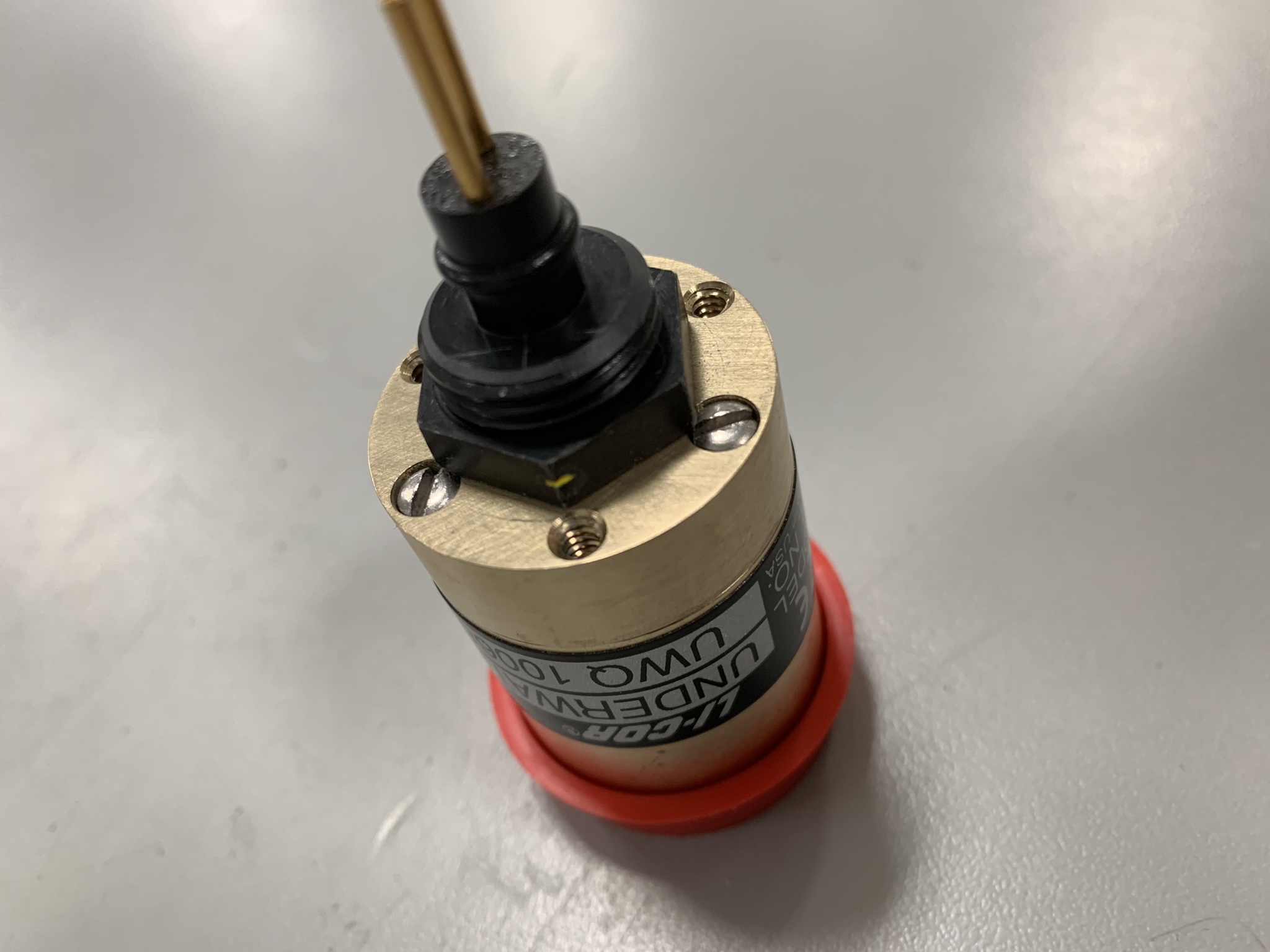
Side view of LI-COR 192 sensor with yellow mark
LI-COR 192 sensor inserted into sensor holder
3. Remove the protective red polymer cap from the face of the Li-192 and reattach the sensor holder assembly to the HydroWiper using a 25mm Allen key.
Side view of Hydro-wiper with LI-COR 192 sensor attached and sensor holder reattached
4. Use a flat head screwdriver to insert the (3) 6-32 X 3/4″ mounting screws provided by LI-COR into the bottom of the sensor holder.
a. Note that the screws were not fully tightened during documentation to maintain the integrity of the shrink tubing on the screws.
Side view of sensor holder with “shrink tube” screws partially inserted
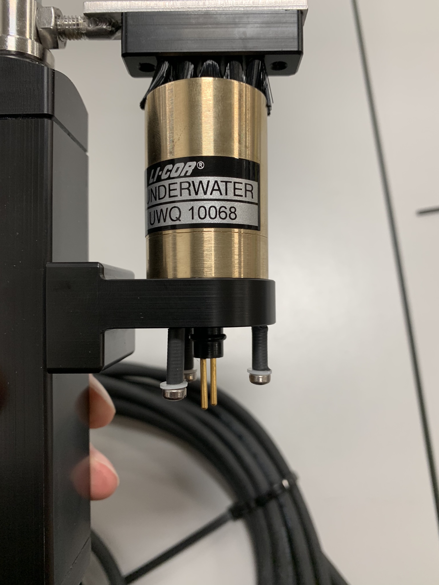
Bottom view of sensor holder with “shrink tube” screws
Attach the hydro-wiper to the mounting block
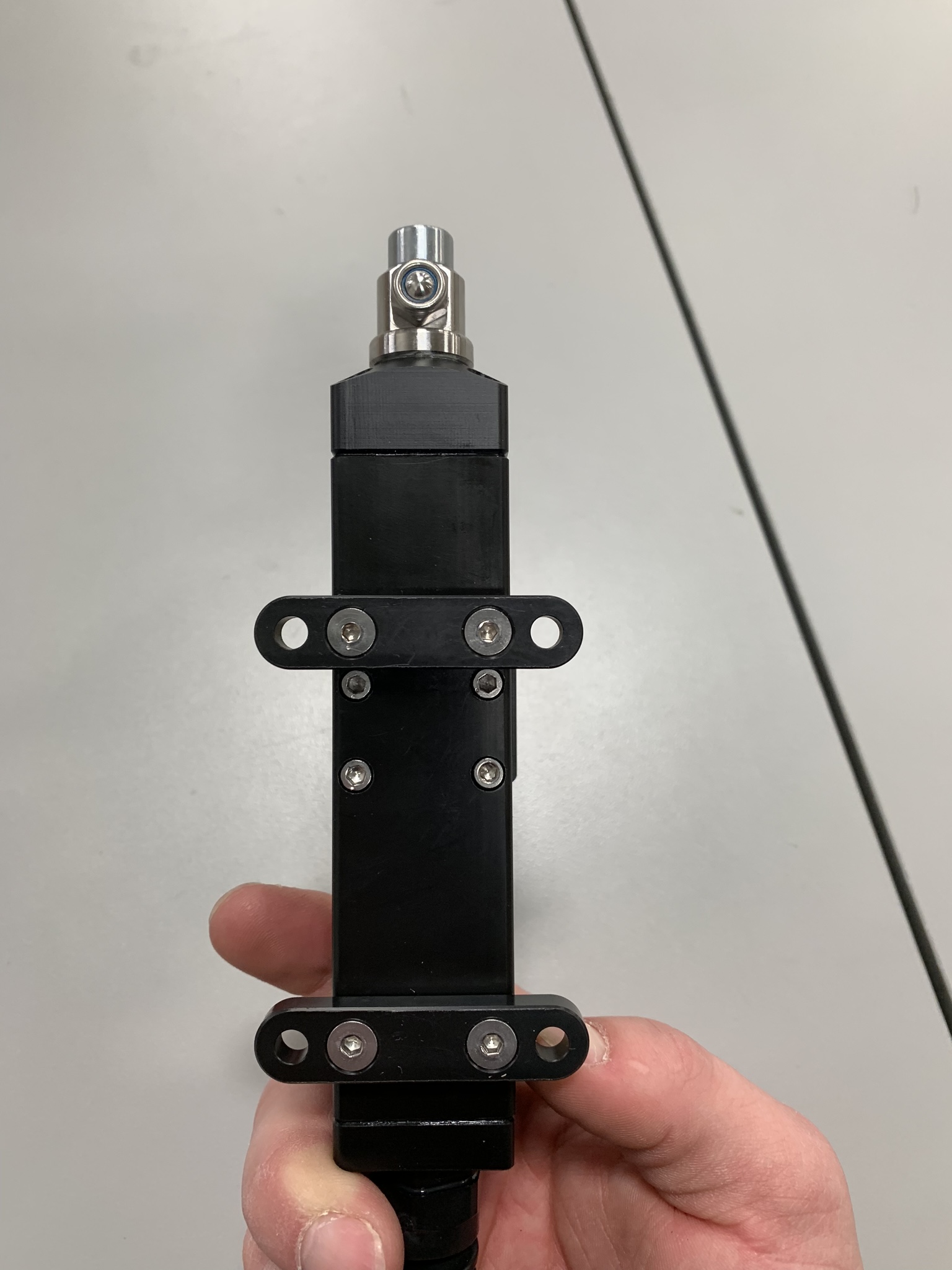
- Use a 3/8″ wrench and a phillips-head screw driver to attach the Hydro-wiper to the mounting block with the remaining (4) 10-32 X 1-3/8″ pan head screws and (4) 10-32″ nylon insert locknuts from the “Hydro-Wiper to Mounting Block” bag.

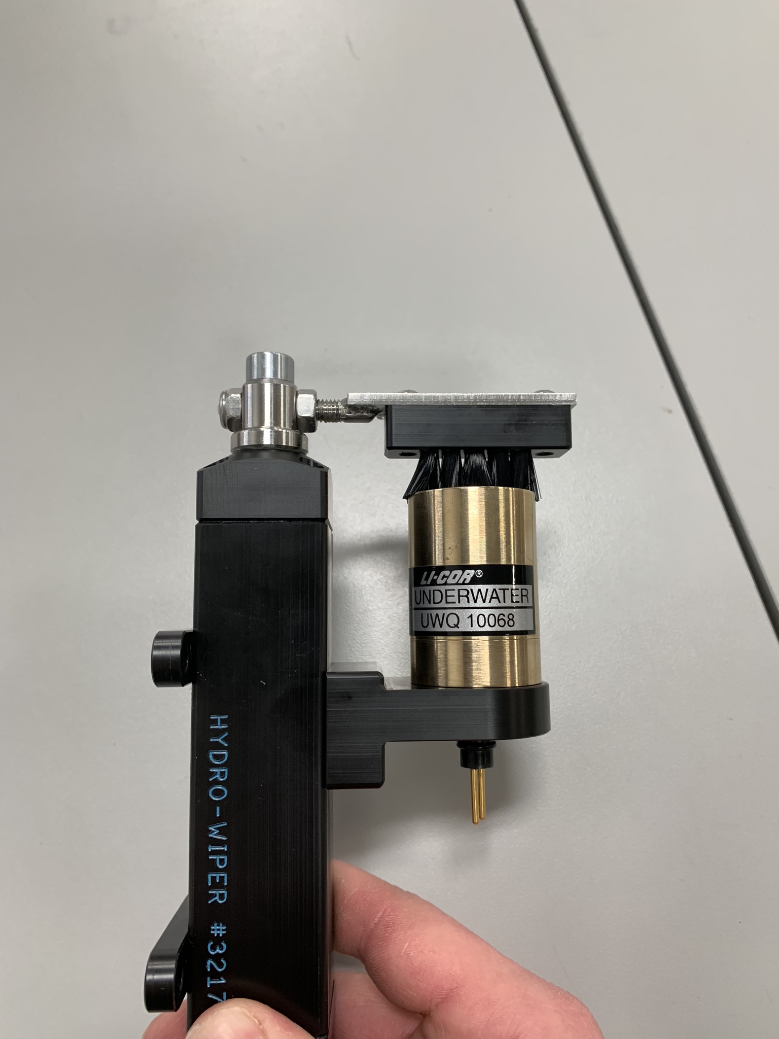
Top view of Hydro-wiper connected to mounting block
Side view of Hydro-wiper connected to mounting block
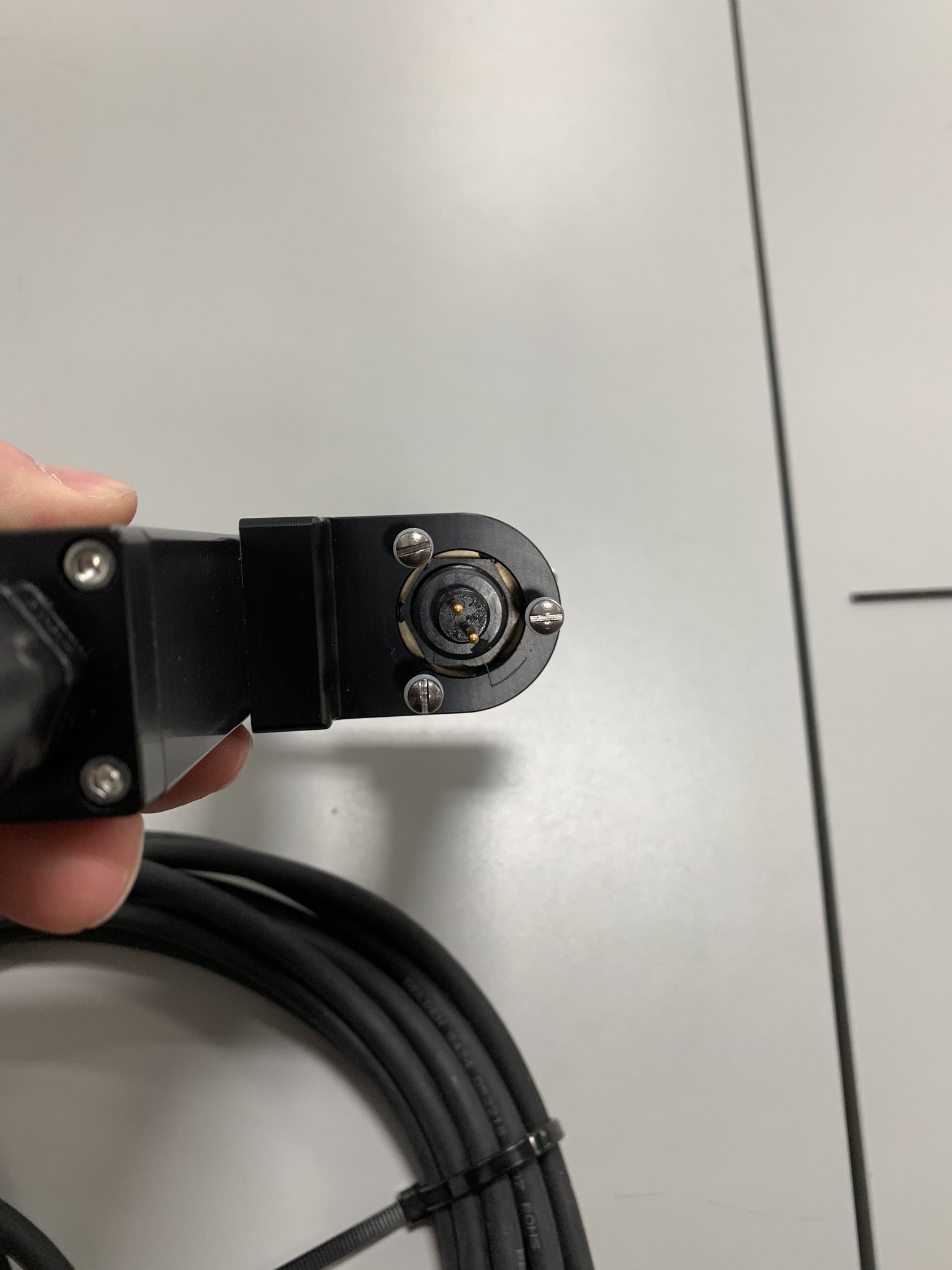
- Connect the LI-COR 192 cable to the sensor.
- Align the exterior dimple of the cable with the yellow mark identified earlier.
- Reversing the cable orientation will not harm the sensor. This will simply cause PAR readings to show negative instead of positive values.
- Press together gently until it fully locks in place. Twist the white cap until hand tight.
- Align the exterior dimple of the cable with the yellow mark identified earlier.

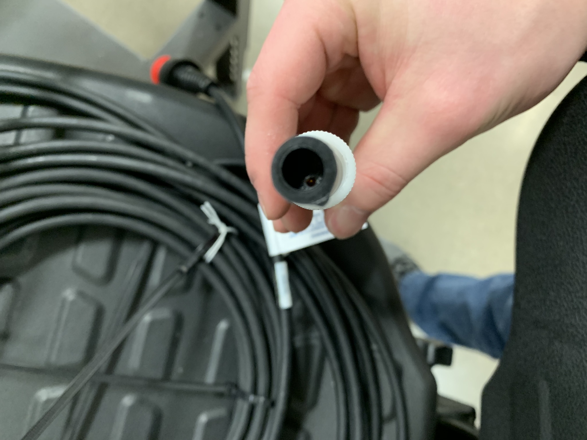
Top view of LI-COR sensor cable with V-shaped protrusion pointing towards the bottom of the image

Top view of Hydro-wiper with LI-COR cable connected to the sensor
Attach a Standard instrument cage to the Unistrut arm
- Use a 7/16″ socket wrench along with a 7/16″ combination wrench to secure the arm to the cage using the (4) 1/4-20 nylon insert nuts, (2) U-bolts and braces from the “Unistrut Arm to Instrument Cage” bag .
- One of the U-bolt ends will need to pass through one of the circular cutouts on the Unistrut for a proper fit.
- Note the instrument cage orientation prior to securing the unistrut so the PAR sensor faces the desired direction. The cage eye-nut will face downwards during deployment.
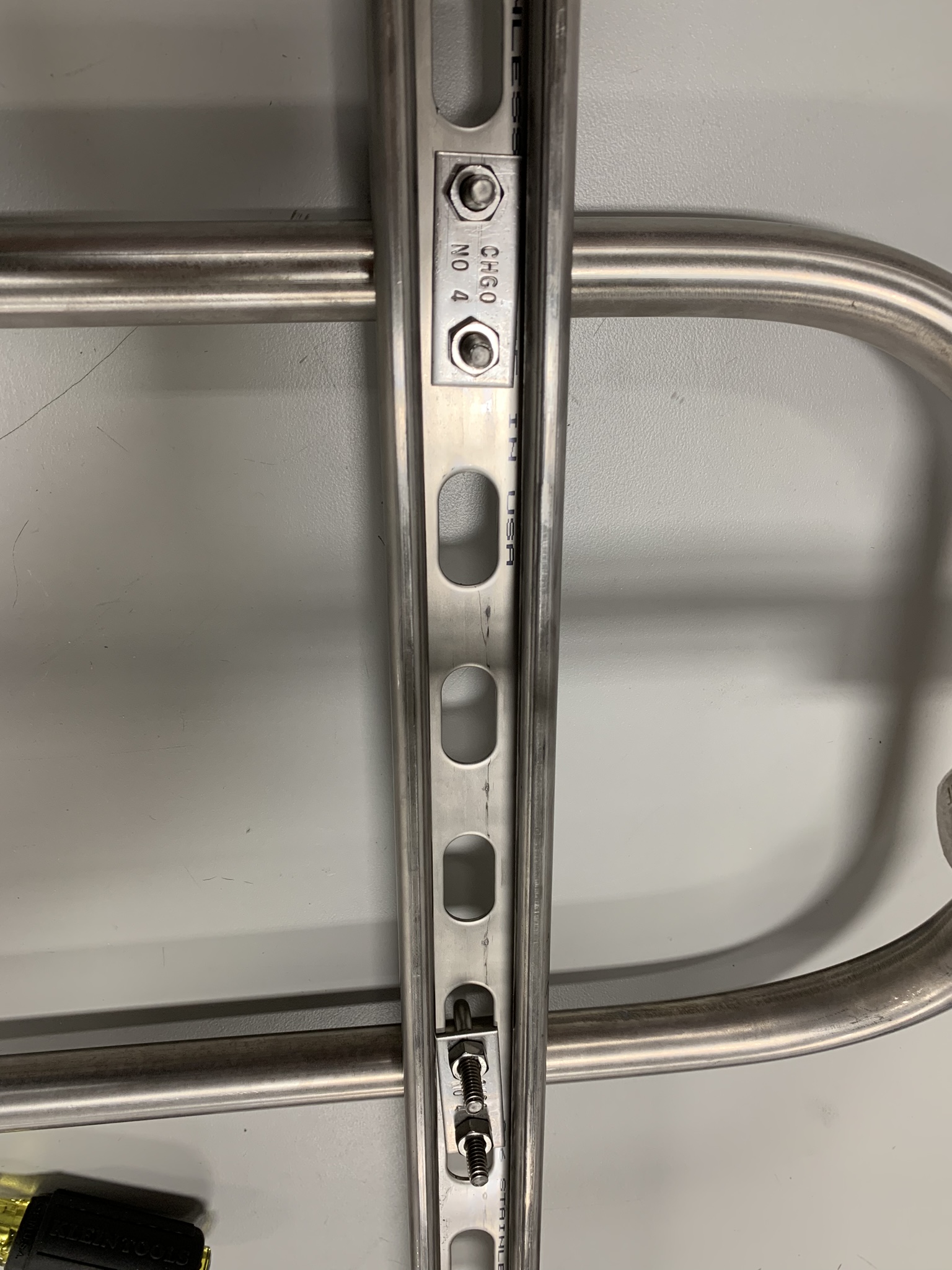
Bottom view of small instrument cage connected to Unistrut arm
Attach a XL instrument cage to the Unistrut arm
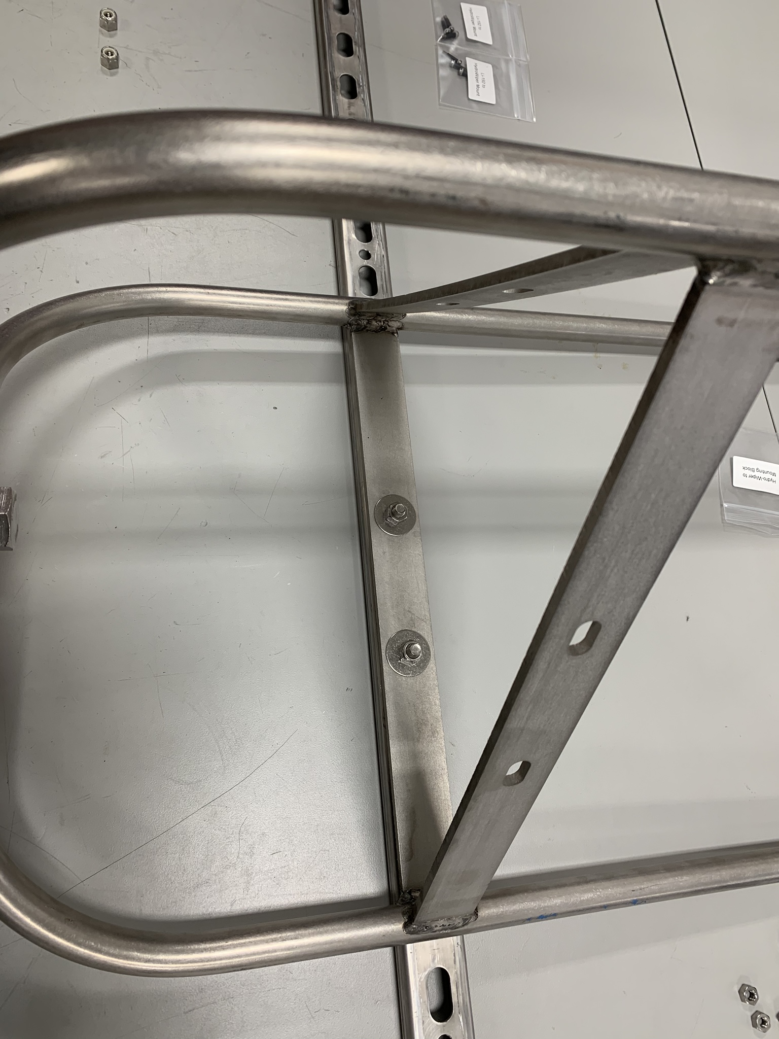
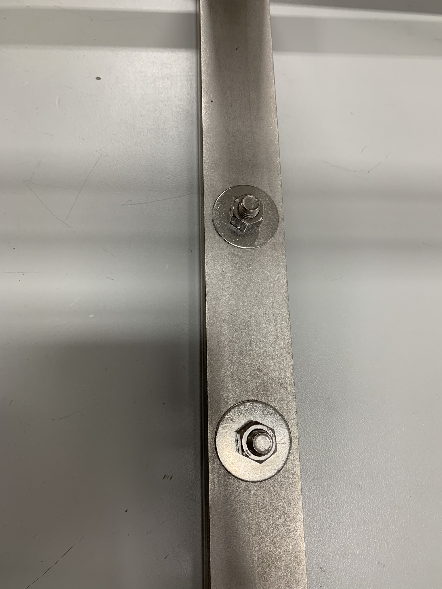
- Use a 3/8″ socket wrench along with a 3/8″ combination wrench to secure the arm to the cage using the (2) 3/8-16 X 1-1/4″ hex cap bolts, (4) 3/8″ fender washers, and (2) 3/8″ nylon insert locknuts from the “Unistrut Arm to XL Instrument Cage” bag.
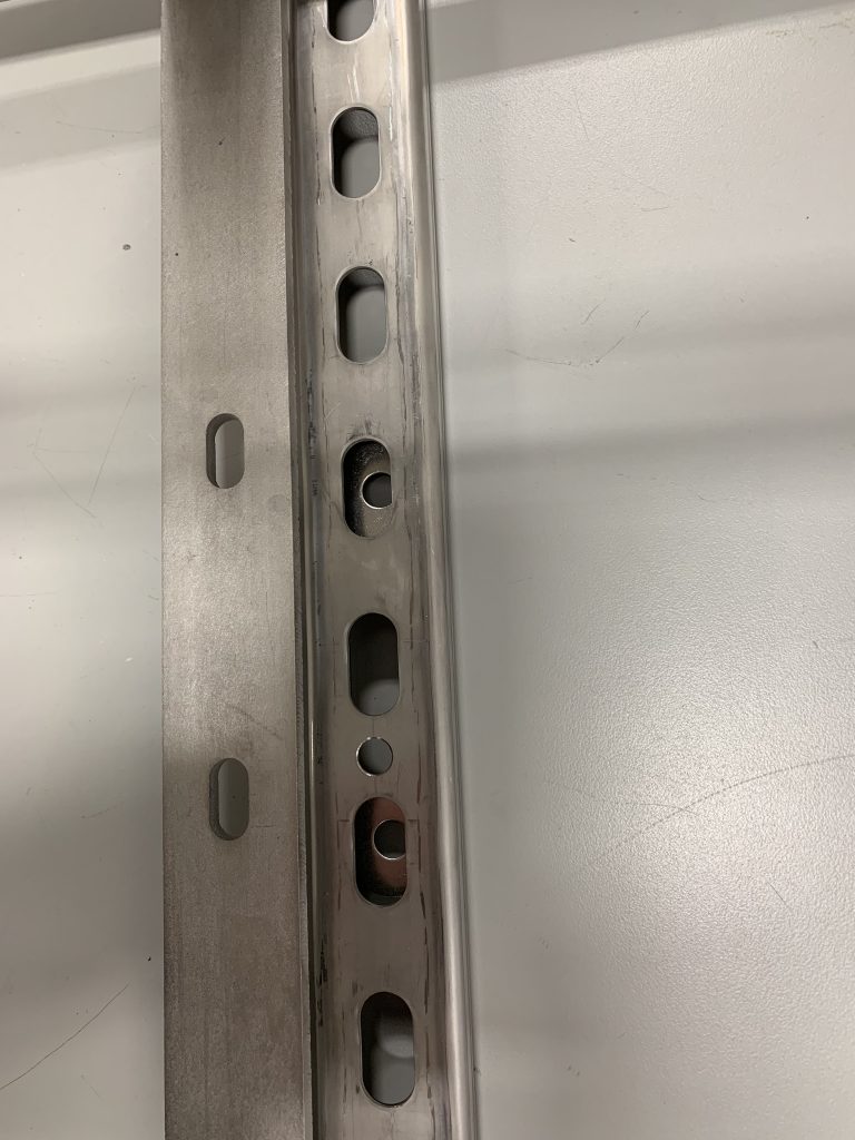
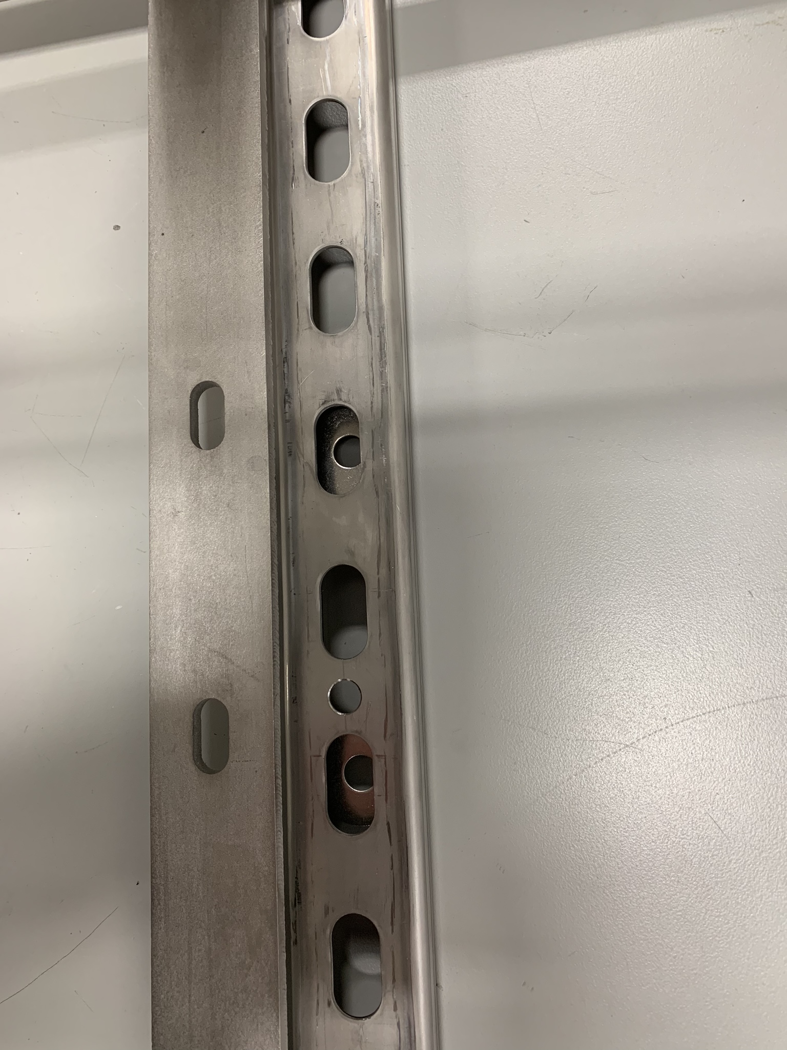
View of large instrument cage placement on Unistrut arm
a. The fender washers must be fed through the end of the Unistrut and aligned with the XL cage crossarm’s mounting holes.
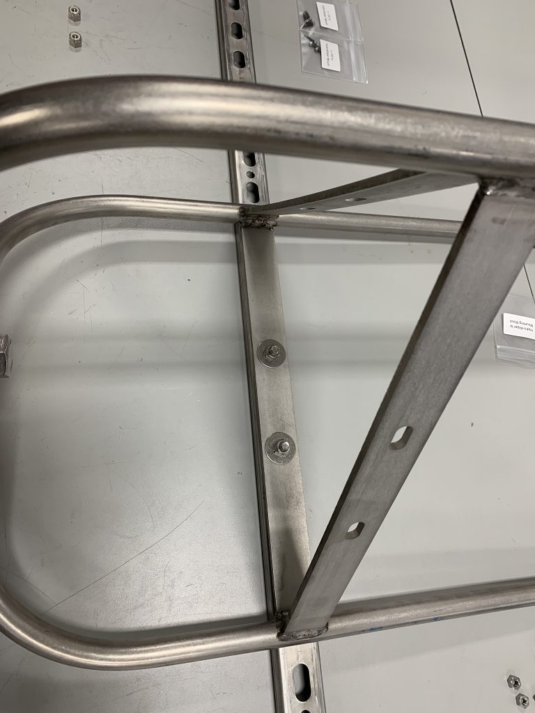
Top view of large instrument cage connected to Unistrut arm
Up-close view of large instrument cage connected to Unistrut arm