
This guide is designed to help you fix common problems associated with failed over-the-air communication between a radio iSIC or SDL data logger and a computer. Radio communication problems can arise for a number of different reasons, including low or no power, weak or out of range radio signal, and improper physical connections.
To troubleshoot this problem, check for communication with iChart software after each step in the procedure below.
1. Check power
- Remove the data logger’s fuses by pressing down on the fuse holder caps while twisting counterclockwise. Visually inspect the fuses for damage. If damage is suspected, use an ohmmeter to confirm continuity throughout the fuses or replace the fuses with known good fuses.
- Look for a green blinking LED above the analog terminal strip immediately after plugging the fuses back in. The light should blink for a few seconds, indicating that the iSIC is properly powered.
- Check the battery terminal connections (red on positive and black on negative) for damage or loose connections.
- Disconnect the battery terminal connectors and check the voltage across the battery using a voltmeter. A reading of at least 12 volts is ideal, but it must be greater than 7.5 volts for radio telemetry to function.
2. Check the base radio station setup
- Make sure the green LED on the AC power adaptor is glowing green. This confirms that 12 VDC is being supplied to the PC interface cable power jack.
- Visually inspect the PC interface cable and MS4 connectors for any broken wires or pins.
3. Check antennas
- Make sure the base radio antenna and data logger antennas are located so the best line of sight to the base is achieved. This will result in the most reliable connection.
- Check the RF connection(s) and make sure no excess moisture and/or water are present. Also check the connectors for any corrosion and examine the cable for any damage.
4. Connect to the base radio using a terminal
- Any terminal emulation program, such as HyperTerminal, can be used to connect the 4100-Base radio. iChart has a terminal emulator located under Advanced | Terminal. To connect using a terminal emulator:
1) Loosen the four screws on the top of the enclosure and remove the lid from the base station.
2) Determine the COM port the base station is connected to and then use the terminal program to connect to the following communication settings:
Data rate – 19,200
Data bits – 8
Parity – None
Stop bits – 1
Flow control – None.
3) Once a connection has been established, press the black button located on the steel plate inside of the base station enclosure.
4) The base radio’s Main Menu should appear. Enter a “2” to edit the call book. The Modem Call Book should appear. Press “Esc” three times to exit the terminal connection. This confirms that the COM port chosen is correct, adequate power is supplied to the radio, and the PC interface cable is functioning properly.
5. Check radio lights
- Each base radio has (3) LED lights that illuminate in various patterns depending on the condition the device is in. The pattern of the lights can be determined by observing their reflections off of the base radio’s enclosure.
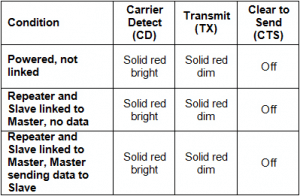
Figure 1: LED Patterns
If none of the procedures isolated and corrected the problem, contact NexSens technical support for additional troubleshooting
REV: 13G18