
In order to calibrate and configure a PONSEL sensor, CALSENS Software and an RS-485 adapter are required. If the cable has been connectorized for use with an SDL500 data logger, a NexSens UW-USB-485R cable is required. If the sensor cable is terminated in flying leads, the In-Situ Modbus Sensor Communication Device Kit can be used.
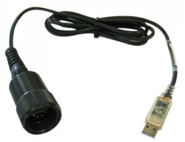
Figure 1: NexSens UW-USB-485R Cable
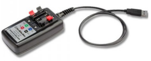
Figure 2: In-Situ Modbus Sensor Device
1. Install Calsens software on the computer.
2. Connect the USB end of the RS-485 Adapter cable to the computer and allow the drivers to install.
3. Connect the sensor to the RS-485 adapter.
- If connectorized, connect the PONSEL sensor’s UW plug to the RS-458 Adapter’s UW receptacle.
- If flying lead, connect the wires to the In-Situ box following the below list.
- PONSEL Blue: Not connected
- PONSEL Red: In-Situ Red (Bottom Left)
- PONSEL Black: In-Situ Black (Bottom Right)
- PONSEL Green: In-Situ Green (Top Left)
- PONSEL White: In-Situ Blue (Top Right)
4. Open CALSENS software on the PC.
5. Select USB from the Select a port dropdown.
6. Select the USB adapter from the Port number dropdown.
- If using the NexSens UW-USB-485R select USB-RS485 Cable.
- If using the In-Situ Communication Device select USB TROLL Com.
7. Uncheck the Remove echo box.
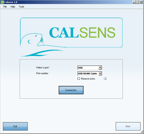
Figure 3: Calsens Connection Screen
8. Click Connection.
9. Click Scan.
10. Once the attached sensor has been detected and appears in the window, click Cancel.
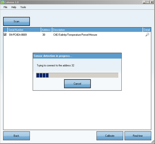
Figure 4: Sensor Found
Once the sensor is connected, it can be configured, calibrated or used for real-time measurements.
To configure the sensor:
11. Click the magnifying glass icon in the Detail column.
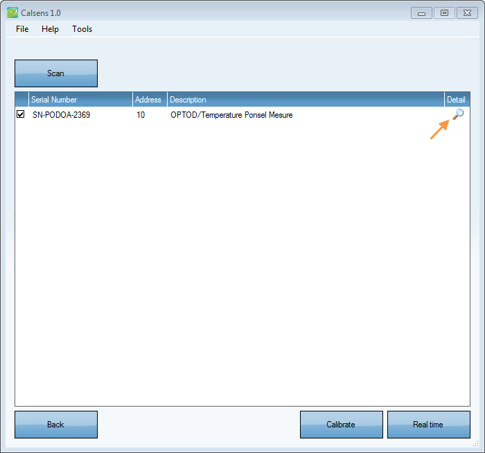
Figure 5: Update Configuration
12. Enter the desired configuration change (e.g. Modbus address, SDI-12 address, etc.) and click the check mark next to the setting to submit. A box will appear to confirm that the change was successful.
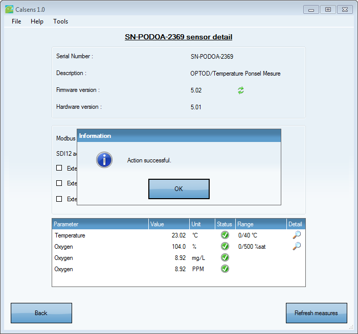
Figure 6: Configuration Update Confirmation
13. Click Back to return to the sensor identification menu.
To calibrate the sensor:
14. Click the Calibrate button at the bottom of the menu.
15. Select the Operator from the drop-down list and choose a parameter to calibrate. Enter any applicable offsets, then click Calibrate to begin.
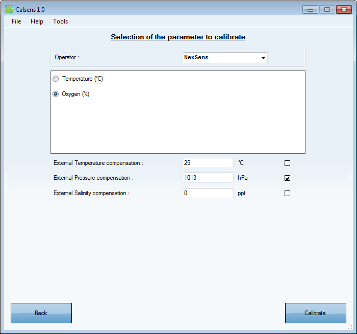
Figure 7: Begin Calibration
16. Look for green check marks to appear in the Status and Stable columns. Then, click Next, and a message will appear to confirm successful calibration.
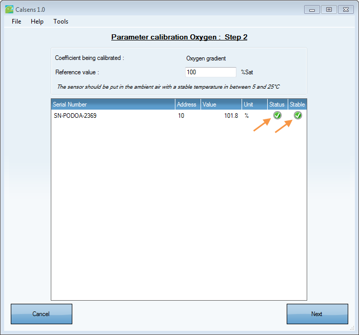
Figure 8: Stable Calibration
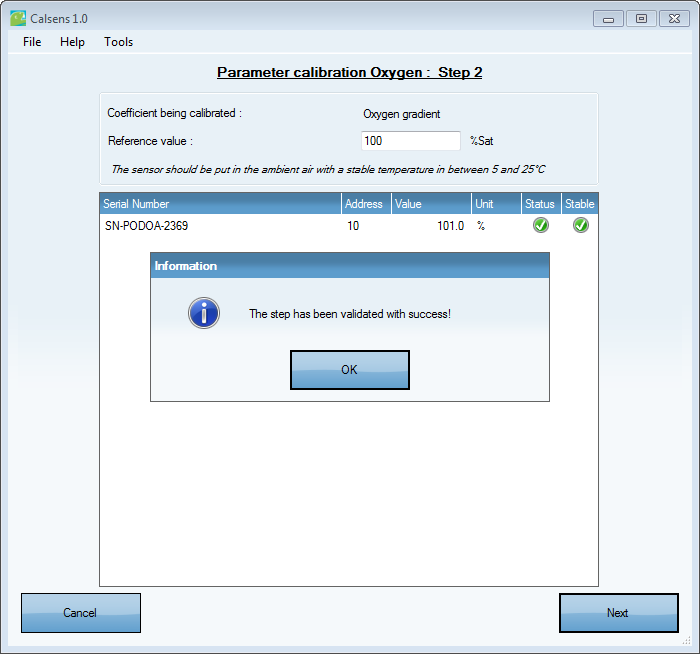
Figure 9: Successful Calibration
17. If the calibration results are satisfactory, click the Validate Calibration button at the Summary screen. A message stating Action successful will confirm that the calibration was validated.
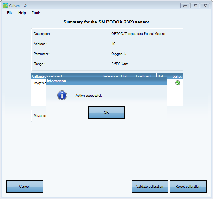
Figure 10: Calibration Validation
18. Click Back to return to the sensor identification menu.
To view real-time data from the sensor:
19. Click the Real time button. Confirm that the Status column shows a green check mark for each parameter. This indicates that the sensor is working properly.
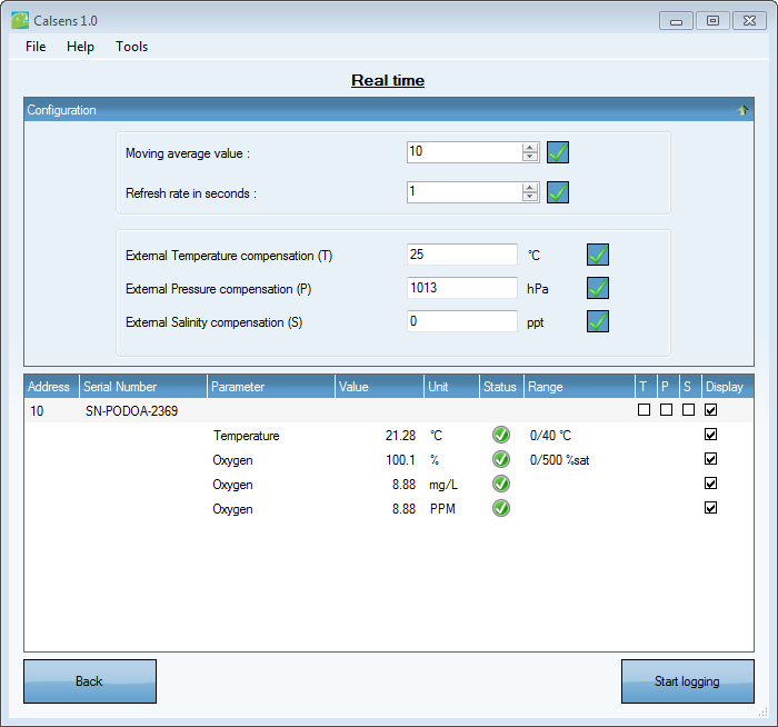
Figure 11: View Real-time Data
20. Click Start Logging to log data from the sensor. Otherwise, click Back to return to the sensor identification menu.
To terminate the connection to the sensor:
21. Click Back at the sensor identification menu to return to the connection menu.
22. Click the Disconnection button and wait until it changes to Connection.
The sensor may now be disconnected.
At any time, the CALSENS instruction manual can be reference by going to Help | Documentation within the software.
REV: 13L21