Before a PC can begin to receive real-time data from the iSIC, a RS-232 Direct Connect Cable must be connected into the iSIC enclosure.
Important: Always remove power from all NexSens communications devices when wiring to the iSIC.
NexSens supplies a variety of permanent RS-232 Direct Connect Cable lengths ranging from 25 ft to 250 ft. For stand alone applications without continuous real time connections, the supplied A72 RS-232 Direct Connect cable may be used to communicate with the iSIC. This cable simply requires connecting the iSIC DB9 connector to the PC COM port.
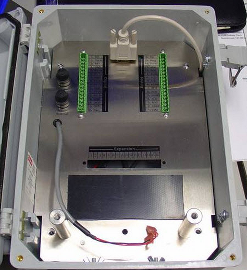
Figure 1: Connect iSIC DB9 connector to COM port
For real time connection to the data logger, A60-A64 Cables will need to be used. If an MS3 connector is located on the outside of the iSIC enclosure, simply connect the MS3 connector on
the A60-A64 DB9 to MS3 cable to the MS3 connector located on the iSIC and the DB9 connector to an open COM port on a PC running iChart software.
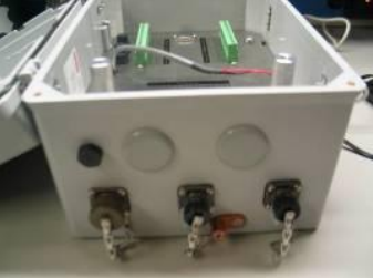
Figure 2: iSIC Enclosure, MS3 is bottom middle
MS3 to DB9
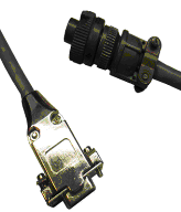
Figure 3: MS3 to DB9
Color | MS3 | Signal | |
Green | A | 5 | GND |
White | B | 2 | Rx |
Blue | C | 3 | Tx |
If an MS3 connector is not available, an A60-A64 DB9 to flying lead cable can be used.
Wiring a direct-connect cable using a flying lead dongle, BTX: CD-MX9M
A direct RS-232 or RS-485 connection to the iSIC can be run through the DB9 port with a BTX CD-Mx9M dongle.
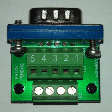
Figure 4: BTX CD-DB9FST Dongle
For RS-232 connection using the iSIC direct connect cable, the following pins are used:
| Color | Dongle | DB9-M | Signal |
| White | Terminal 2 | Pin 2 | Tx (iSIC to PC) |
| Blue | Terminal 3 | Pin 3 | Rx (PC to iSIC) |
| Green | Terminal 5 | Pin 5 | GND |
For RS-485 connection using a supplied cable, the following pins are used:
| Dongle | DB9-M | Signal | |
| Terminal 5 | Pin 5 | GND | |
| Terminal 6 | Pin 6 | RS485A | |
| Terminal 8 | Pin 8 | RS485B |
Secure the dongle to the iSIC DB9 port. Be sure to tighten the screws with a screwdriver.
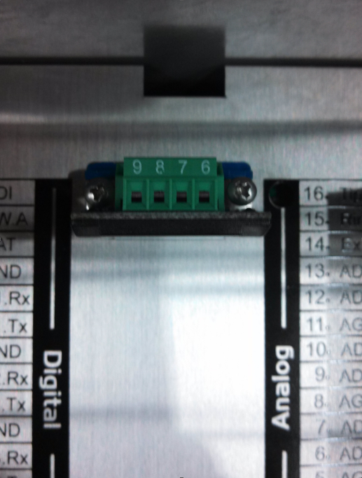
Figure 5: Tighten dongle with screwdriver
REV: 13J18
