
In iChart, go to the Advanced | iSIC | iSIC menu. The iSIC Setup dialog box will open:
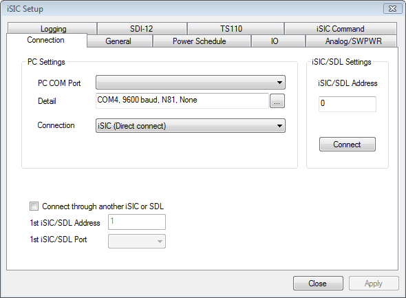
Figure 1: iSIC Setup window
The first screen gives the iSIC connection options. Enter the COM port and connection method of the desired iSIC as well as the iSIC Address. For example, if trying to connect to a 2100-iSIC with a modem connected to COM3, select 2100-iSIC from the connection drop down menu, and COM3 from the COM port menu. The address will typically be “1” unless connecting to a 4100-iSIC. When this information has been correctly entered, click the Connect button.
After connecting, click on the Analog tab.

The analog tab allows for reading the actual voltage on each analog channel as well as enabling the 12V switches. SW12VA is located on the green digital connector of the iSIC. Analog channels 0 to 7 (singled ended SE0-SE7 or differential DE0-DE3) are located on the analog green terminal strip. SE8-15 or DS4-7 are only available on analog expansions and DO and temperature are only available on dissolved oxygen expansions.
When selecting single ended channels, values ranging up to a few hundred are normal when no sensor is connected to the data logger. In differential, these readings should be zero.
The importance of being able to turn on the SW12VA is that many analog sensors use the SW12VA as their power supply. This check box must be checked in order for the sensors to work properly.
When troubleshooting invalid readings from an analog sensor, the first step should be to determine if the sensor is outputting the correct voltage reading.
Note: 4-20mA sensors use a 56 Ohm resistor, so their voltage range will vary from 224 mV at 4 mA (4 mA * 56 Ohm = 224 mV) to 1120 mV (20 mA * 56 Ohm = 1120 mV).
REV: 13G01