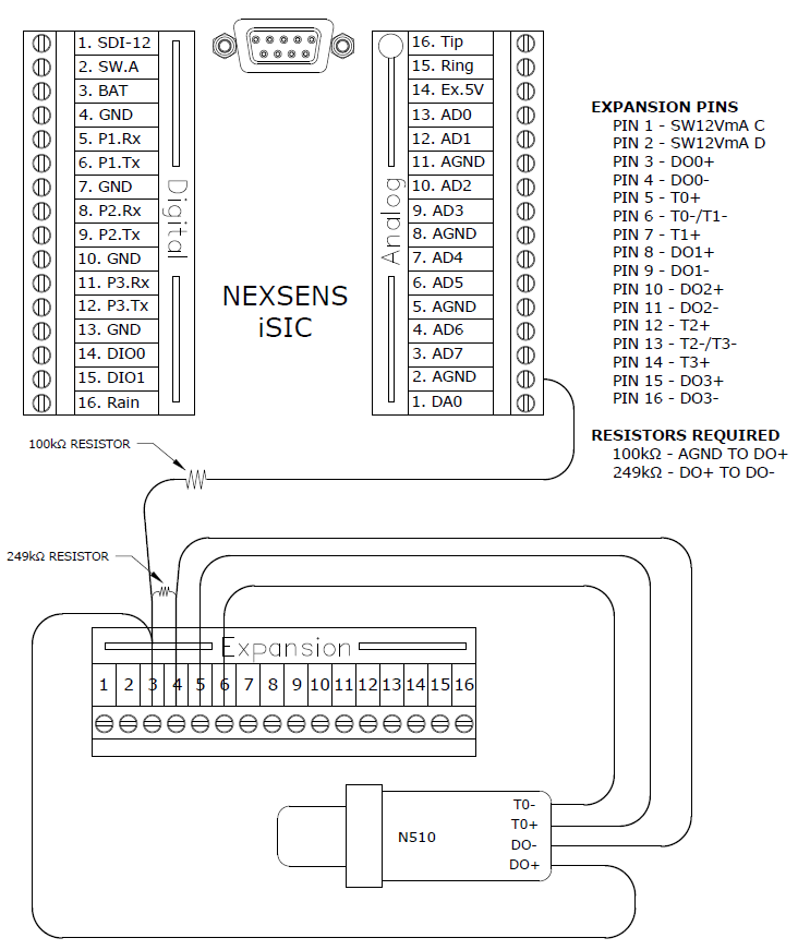
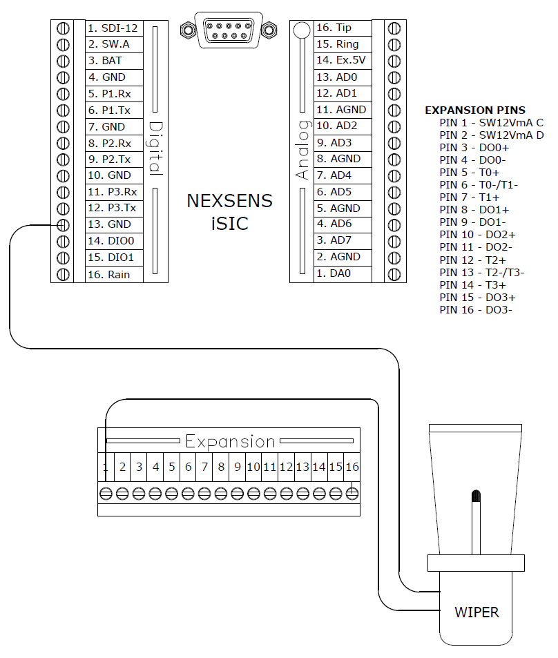
The temperature and dissolved expansion connector allows for the addition of multiple temperature and dissolved oxygen sensors to a system. See the diagrams below for exact signal pins.
Dissolved Oxygen Sensors
The dissolved oxygen expansion connector allows for four dissolved oxygen sensors to be added to a system. Connect the positive signal wire to the (+) and the negative wire to the (-) pin on the expansion connector, see the diagram below:

Figure 1: Adding Dissolved Oxygen Sensors to Expansion
The diagram above shows a N510 connected to the DO0, and T0 channels on the temperature and dissolved oxygen expansion. Up to four N510’s can be added to a system using DO0-DO3, and T0-T3.
Temperature Sensors
The temperature and dissolved oxygen expansion connector also allows the direct interface of the N110 temperature sensor to the iSIC using T0 –T3. Simply connect the sensor’s positive lead to the (+) and negative lead to (-) pins of the same T channel as shown in the diagram below:

Figure 2: Adding DO Temperature Sensors to Expansion
The wiring above shows a N110 sensor connected to pins 5 and 6, temperature channel T0 on the temperature and dissolved oxygen expansion. Multiple N110 may be added to a system by wiring the N110 to temperature channels T1, T2, and T3.
12V Switches
The dissolved oxygen expansion connector also has two 12V 200mA switches, which can be used to power specific devices and sensors, such as probe wipers or cell modems. The switches turn on before a reading is taken and turn off after a reading is taken to conserve battery life.
The diagram below shows a wiper using SW12VmA C. One wire is connected to the switch pin and the other wire must be connected to a ground on the digital terminal strip. An additional device can be added using SW12VmA D, and a ground on the digital terminal strip. Wipers can be used with the N510 to provide accurate measurements in muddy or stagnant water.

Figure 3: Adding 12V Switches to Expansion
REV: 13G11
