It may be necessary to remove the PCB (Printed Circuit Board) from the mounting plate for inspection or replacement.
1. Remove all attached wires from the back of the PCB. Note that the specific wires will vary depending on the communication available.
Note: Record all wire locations before removal if replacing the board.

Figure 1: Wire Removal (3100-iSIC Shown)
2. Remove the nut and lock washer from the PCB.

Figure 2: Nut Removal
3. Remove the 4 Philips head screws and lock washers and two jack screws (select models only) from the front of the PCB.

Figure 3: Plate Removal
4. Remove the 4 Philips head screws and lock washers from the front of the PCB to release the communication standoffs if applicable.
Note: If a radio is being removed the radio PCB must be gently removed pulled out of the iSIC PCB’s connector.

Figure 4: Communication Device Removal
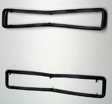
5. Gently pull the black gaskets around the green phoenix connectors off.

Figure 5: Gasket Removal
The PCB is now free from all mounting and can be inspected or replaced as is required.
REV: 13G29
