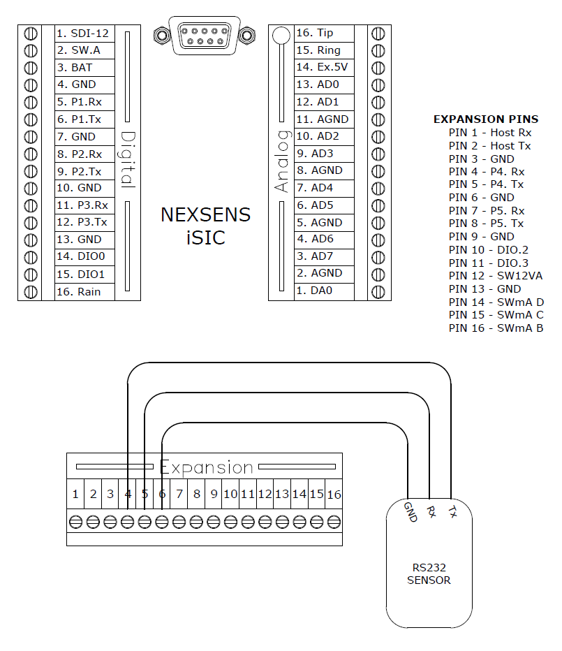
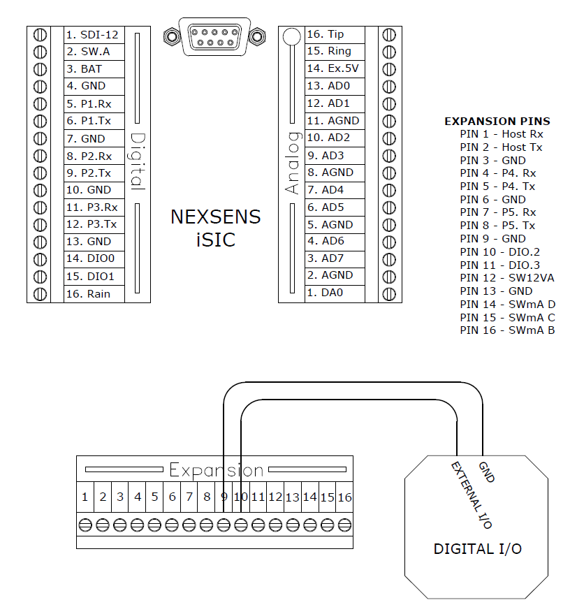
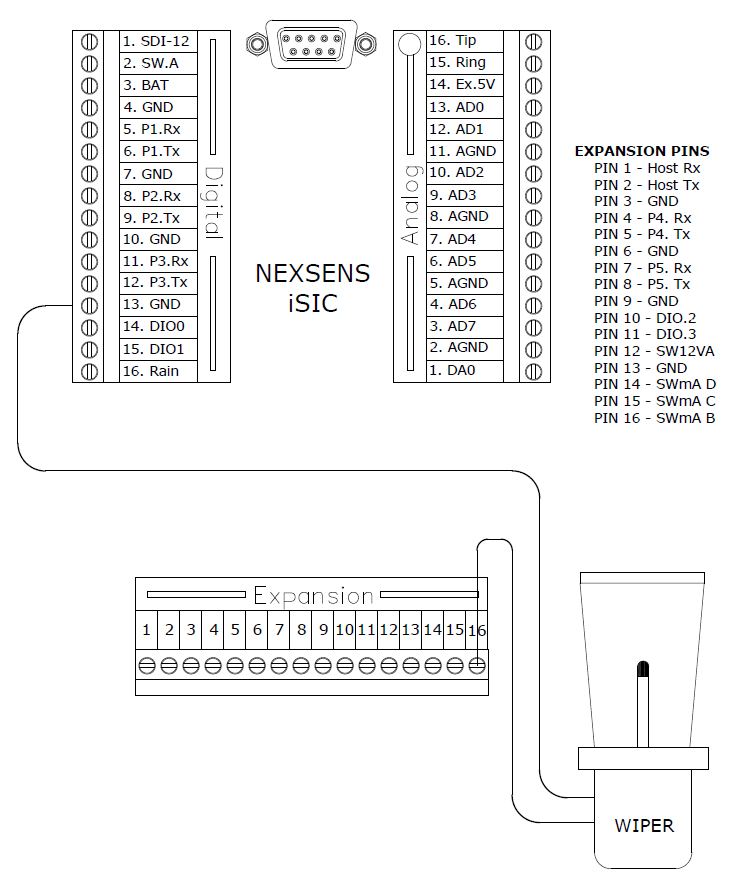
The digital expansion connector allows for the addition of multiple RS232, and generic digital I/O sensors, as well as a main communication port. See the diagrams below for exact signal pins:
RS232
The digital expansion connector allows for two additional RS232 sensors. These ports operate the same as those located on the digital terminal strip.

Figure 1: RS232 Sensor wiring into Digital expansion
The diagram above shows an RS232 sensor connected to port 4 of the digital expansion. An RS232 sensor may also be connected to port 5.
Main Communication Port
Pins 1, 2, and 3 on the digital expansion connector are used for a main communication port and are useful when a system cannot use the DB9 connector for communicating with the iSIC, such as when using a serial-to-flying-lead cable.

Figure 2: Wiring Computer Communication Port to Digital Expansion
The diagram above shows a PC interfacing with the iSIC using the digital expansion. Connect the Rx wire to pin 1, the Tx wire to pin 2, and GND to pin 3.
If using an RS232 iSIC Interface Cable Cable:

Figure 3: Using an RS232 iSIC Interface Cable
Digital I/O
The digital expansion connector also allows for two more additional digital I/O sensors. These additional sensors operate in the same way as those located on the digital terminal strip.

Figure 4: Wiring Digital Input/Output into Digital Expansion
The diagram above shows a digital I/O sensor connected GND, pin 9, and DIO.2, pin 10, on the digital expansion. Another digital I/O sensor can be added using DIO.3, pin 11 and GND. These DIO pins operate the same way as DIO.0 and DIO.1.
12V Switches
The digital expansion connector also has three 12V 200mA switches and one 12V 1A switch which can be used to power specific devices and sensors, such as probe wipers or cell modems. The switches turn on before a reading is taken and turn off after a reading is taken to conserve battery life.

Figure 5: Adding Wiper to Digital Expansion
The diagram above shows a probe wiper connected to SWmA B. One wire is connected to the switch pin and the other wire must be connected to a ground on the digital terminal strip. Additional devices can be added using SWmA C and D, and a ground on the digital terminal strip. SW12VA should be used for devices requiring a higher current to operate, such as a cellular modem.
REV: 13G11
