High gain antennas are used for all deployments with iSIC data loggers using telemetry. The antennas are mounted on the iSIC box. If the antenna is to be mounted on a pole, the mounting pole should have a diameter up to 2-1/2 inches and have a height as high as practical for the application; also use a cable length that appropriately fits the mounting pole. Nexsens offers various lengths of RF cable, ranging from 2 ft to 100 ft in length:
Antennas can be connected to an iSIC using NexSens RF cables. Additionally, an A38 ground kit and A39 lightning arrestor is recommended for installations where damage due to lightning may occur.

Figure 1: NexSens Micro & Low Loss RF Cables
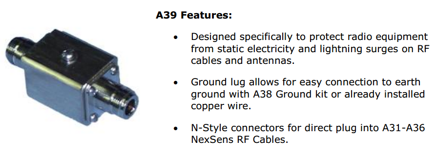
Figure 2: A39 Features
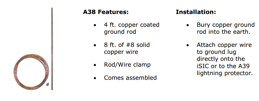
Figure 3: A38 Features
A49 Cellular Antenna

Figure 4: NexSens A49 High Gain Cellular Antenna
The A49 high gain cellular antenna is an excellent choice for remote communication via GPRS/GSM, EDGE or CDMA cellular transmission. It includes the antenna and a mounting bracket, a whipless design and N-style female RF connector for use with standard RF cables. It features an821-896 MHz frequency range, weatherproof ABS housing and 3dBi nominal gain.
A44 Radio Antenna
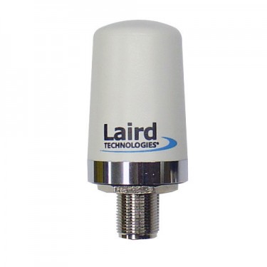
Figure 5: NexSens A44 High Gain Radio Antenna
The A44 high gain antenna features a 902-928 MHz frequency range, weatherproof ABS housing, 3 dBi nominal gain, and an N-style connector for quick connection to NexSens RF cables. The low-profile antenna is 2.30″ tall. The chrome bushing with o-ring ensures a durable seal to allow for long-term deployments in harsh environments. This high gain antenna receives and transmits in any direction, making it the preferred antenna for most short range (up to 1 mile line-of-sight) spread spectrum radio applications.
A41 Omni Directional Antenna
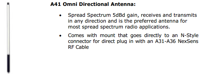
Figure 6: A41 Omni Directional Antenna Features
To mount the A41 Omni antenna: 1) slide the mounting brackets (supplied with the antenna) over the end of the antenna; 2) space the brackets about 6 inches apart; 3) tighten the set screws and slide the assembly over the mounting pole; 4) tighten the U-bolts after the antenna has been aligned in a vertical position.
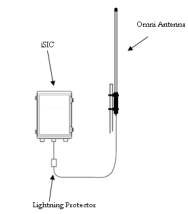
Figure 7: Omni Antenna Setup
Mount a Lightning Protector below the enclosure and install an RF cable between the lightning protector and antenna.
A46 Yagi Directional Antenna
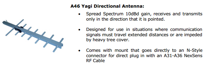
Figure 8: A46 Yagi Antenna
To mount this antenna: 1) mount the U-Bolt to the end of the antenna boom; 2) slide the U-Bolt over the mounting pole; 3) point the antenna in the direction of either the cell tower or iSIC base station; 4) tighten the U-bolts after the antenna has been aligned in the correct position.
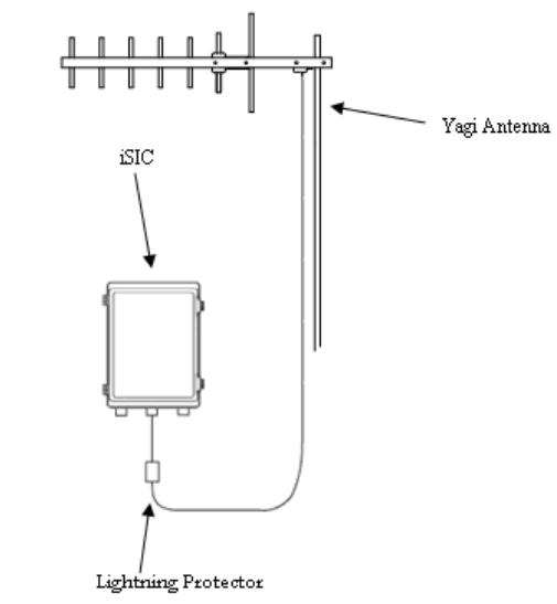
Figure 9: Yagi Antenna Setup
Mount a Lightning Protector below the enclosure and install an RF cable between the lightning protector and antenna.
REV: 13G12
