Replace a Battery in a CB-Series Data Buoy (CB-X3L Lid)
The 12V sealed lead acid (SLA) batteries installed in the data well of CB-Series buoys may require replacement when the charge falls below ~10V or every 2-3 years as their integrity declines with age. This guide shows the steps to replace the A05 12V 28 A-Hr battery commonly equipped in harnesses with one to four A05 units (depending on buoy capacity) on NexSens CB-Series data buoys.
Caution! While assembling the battery harness, insulate any loose battery leads, wrenches, or other tools with electrical tape to avoid shorting the batteries against the data well and potentially causing injury. Ensure the vent is clear of all obstructions, as a clogged vent can cause high-pressure combustible gas build-up in the well due to outgassing from the batteries. DO NOT use power tools to remove the plate.
Tools Required
- Electrical tape
- 9/16″ socket wrench with extension
- 10mm socket wrench with extension
- Fully charged replacement battery
- Digital voltmeter/multimeter
- New desiccant (recommended)
Data Well Lid Removal
- Disconnect the PWR OUT cable from the data logger and the SOLAR IN cable from the CB-X3L plate.
- Cover all plugs and receptacles to prevent moisture and debris from the port pins and O-rings.
- Remove the buoy’s solar tower to gain access to the data well.
- For the CB-150, CB-250, and CB-450: Remove the (6) bolts and lock washers holding the solar tower to the buoy using a 9/16″ socket or wrench.
- For the CB-650, CB-950, and CB-1250: Remove the three clevis pins securing the solar panel tower legs to the buoy hubs and carefully lift upwards to detach the assembly.
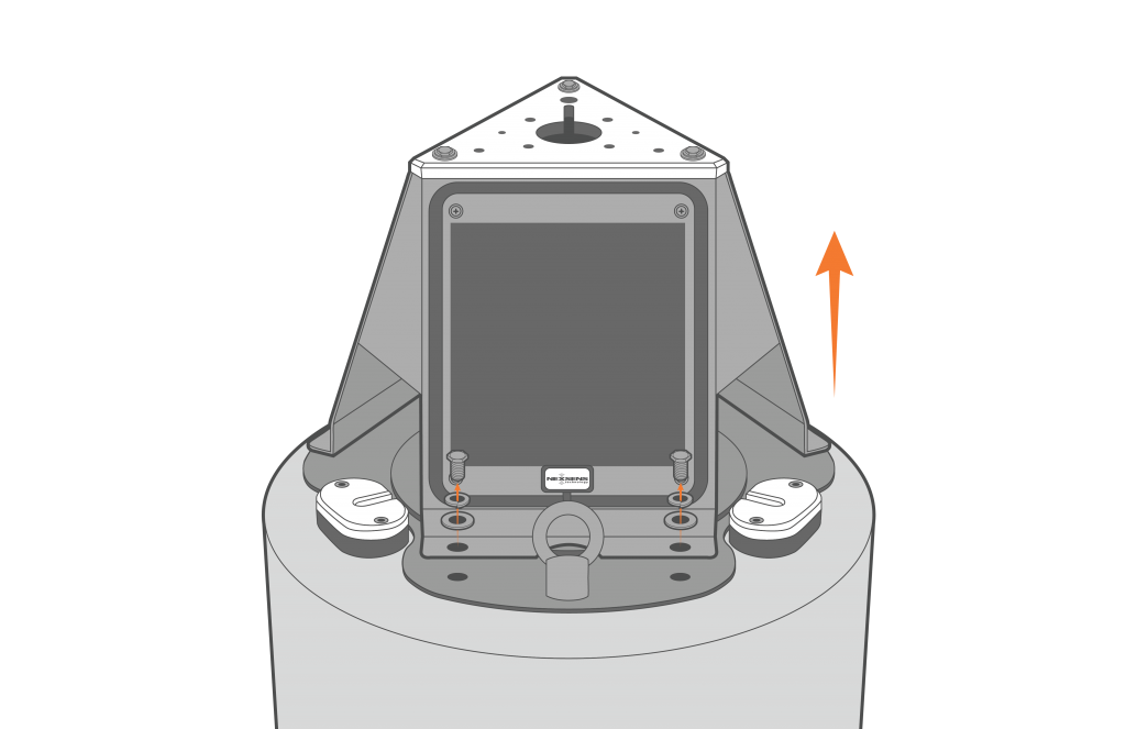
Figure 1: Remove solar tower from CB-150/250/450 buoys.
- Remove the (8) bolts with lock washers from the buoy plate using a 9/16″ socket or wrench.

Figure 2: CB-X3L plate removal.
Battery Removal
- Lift the buoy plate off the data well and disconnect the Molex connector running between the solar regulator and the CB-X3L plate.
- This will expose the data well where the battery and solar regulator are installed.
- Remove the foam coverings to expose the battery harness.
- Remove the two nut, lock washer, and flat washer pairs securing the regulator bracket to the battery mount posts (threaded rod).
- Using caution to avoid short-circuiting the battery terminals to the walls of the buoy well, remove the regulator’s ring terminals from the battery using a 10 mm socket or wrench.
- Set aside the terminal bolts for use later.
- Lift the regulator bracket off of the threaded rod and remove it from the data well. The battery should now be accessible.
[Only for systems with 2 or more batteries]
- Using a 10 mm socket or wrench, carefully remove one of the two ring terminal cables connected to the battery. Immediately cover the loose cable end with electrical tape to prevent it from contacting the data well and short-circuiting.
- Repeat this step for the other battery terminal and cable, removing the old batteries one by one as they are disconnected.
- Remove the used battery from the data well.
- If it does not easily lift out, some of the wedged foam surrounding it may need to be removed.
- Remove the ring terminal cables from the original battery terminals using a 10mm socket wrench.
- Keep the terminal bolts and re-use them in the new battery.
New Battery Installation
[For systems with a single battery]
- Lower the new battery into the data well.
- It may be necessary to adjust the foam for a proper fit.
- Skip ahead to Step 3, “For All Systems”
[Only for systems with 2 or more batteries]
- Discard any pre-installed hardware on the new battery terminals. Using the original battery terminal bolts and a 10mm socket wrench, tighten the ring terminal cables to the new battery.
- Make sure that the cables point toward the corners of the battery.
- Always insulate the detached cable leads to prevent short-circuiting the battery during installation.
- Ensure that the opposite ends of the ring terminal cables are still insulated with electrical tape.
- All batteries except the battery on top of the stack should have neoprene strips adhered in line with the terminals to maintain spacing.
- Lower the first battery into the bottom of the data well. Stack the second, then third and fourth batteries (if applicable), attaching the previous battery’s ring terminal cable to the corresponding battery terminal above it each time.
[For all Systems]
- Once the final battery is installed in the data well, orient the solar regulator bracket so that the ring terminal connections to the topmost battery are on the same side.
- Slide the solar regulator bracket back on to the threaded rod and lower it until it is resting on top of the new battery.
- Using a 10 mm socket or wrench, tighten each ring terminal from the solar regulator to its corresponding battery terminal.
- Ensure the leads face inwards toward the center of the battery.
- Place the flat washer, followed by the lock washer and nut, over the threaded rod, and hand-tighten the regulator bracket to the top battery.
- Using a 9/16″ socket or wrench, tighten down the regulator bracket until it is snug and the lock washers are flattened.
- Do not over-tighten, as this may bow or crack the regulator bracket.
- Replace the foam inserts in the data well. Feed the Molex connector through the foam insert with the small-diameter hole.
Buoy Plate Re-installation
Note: It is recommended that a new desiccant be added and the large O-ring be cleaned with a lint-free wipe and lightly greased with O-ring grease.
- Reconnect the Molex connector to the bottom of the CB-X3L plate.

Figure 3: CB-X3L Molex connection.
- Align the plate with the mounting holes on the buoy and verify that the large O-ring is in good condition, clear of debris, and lightly greased.
- Reattach the plate using a 9/16″ socket or wrench and the original set of bolts and lock washers.
- Tighten in a cross pattern as shown below.
 Figure 4: CB-X3L plate re-installation. | 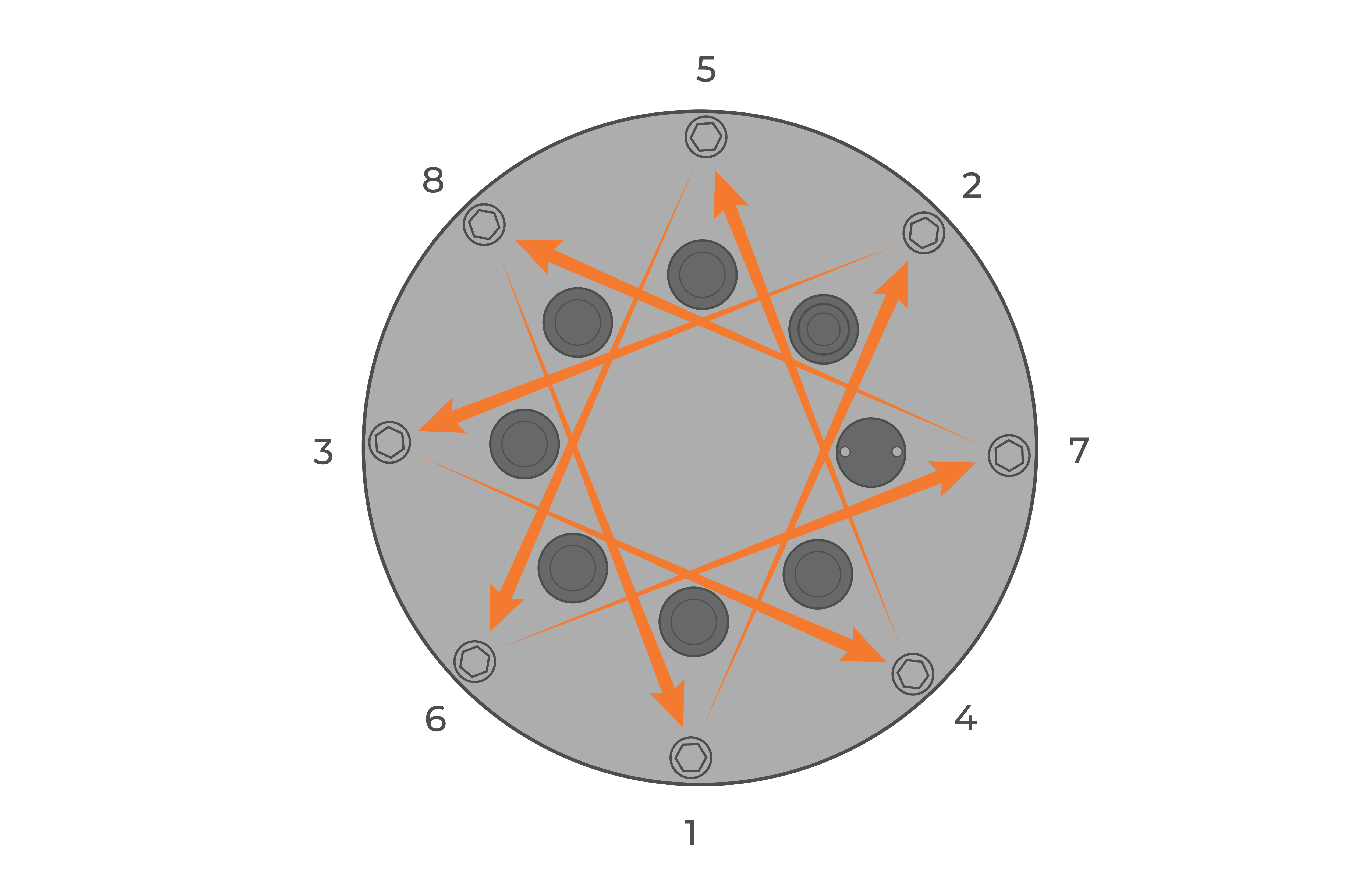 Figure 5: Bolt down the plate in a crisscross pattern |
- Re-attach the buoy’s solar tower.
- Using a voltmeter, measure the voltage between pins 3 (V+) and 4 (GND) of the PWR OUT cable. This should read close to the voltage of the new battery (~12V to 15V).
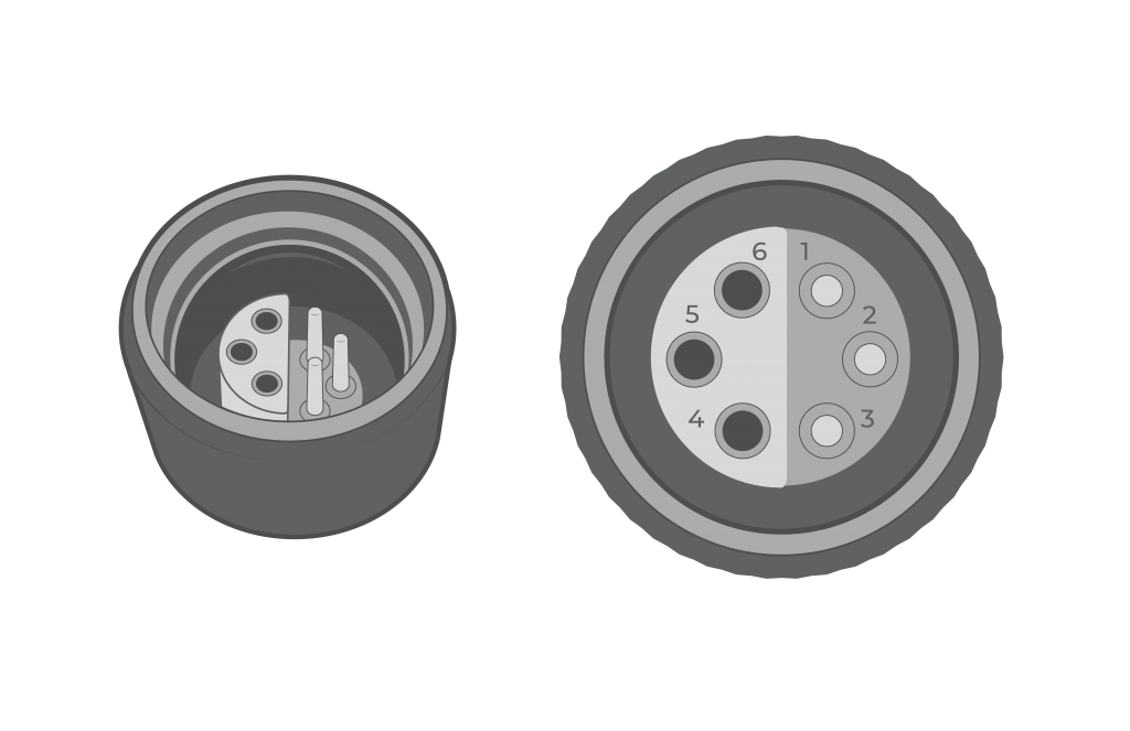
Figure 6: PWR OUT cable pin numbering on CB-X3L plates.
- Once the voltage is confirmed, reconnect the solar tower cable to SOLAR IN and the PWR OUT cable to the data logger.
- Place the entire system outside and review the Primary Power parameter from the data logger for multiple hours. On a clear, sunny day, the voltage should reach between 14 and 14.5V in a “charging state.”