
Install a SIM Card into an X2-CB/X2-CBMC Cellular Logger
While it is always recommended that a SIM card be sent to NexSens for installation prior to shipment, in some cases it may be necessary for an end user to install a SIM card.
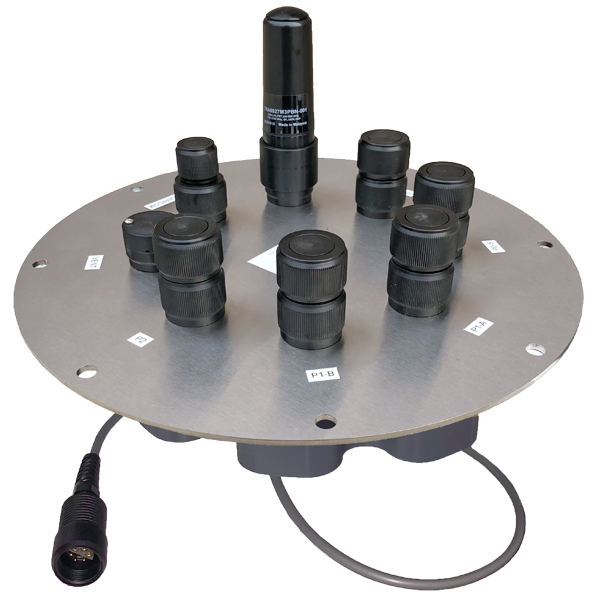
Figure 1: X2-CB data logger.
Caution!!!- Be sure to statically ground yourself prior to touching any of the electronics inside the X2 logger!
Tools Required
- 9/16″ socket wrench
- Phillips head screwdriver
Instructions
- Disconnect the 6-pin solar panel or UW-6 USB cable from the X2-CB/X2-CBMC SOLAR/COM port to remove power from the data logger.
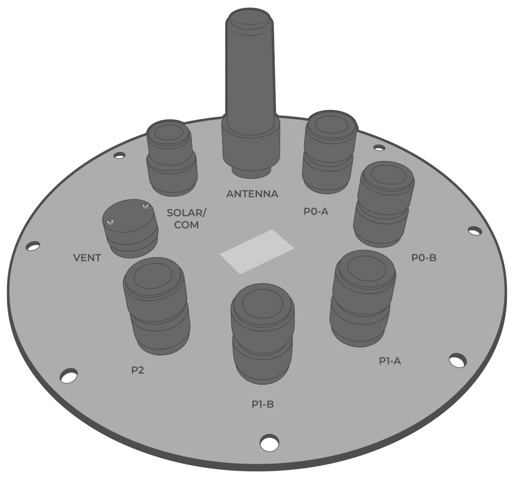
Figure 2: X2-CB port configuration. |
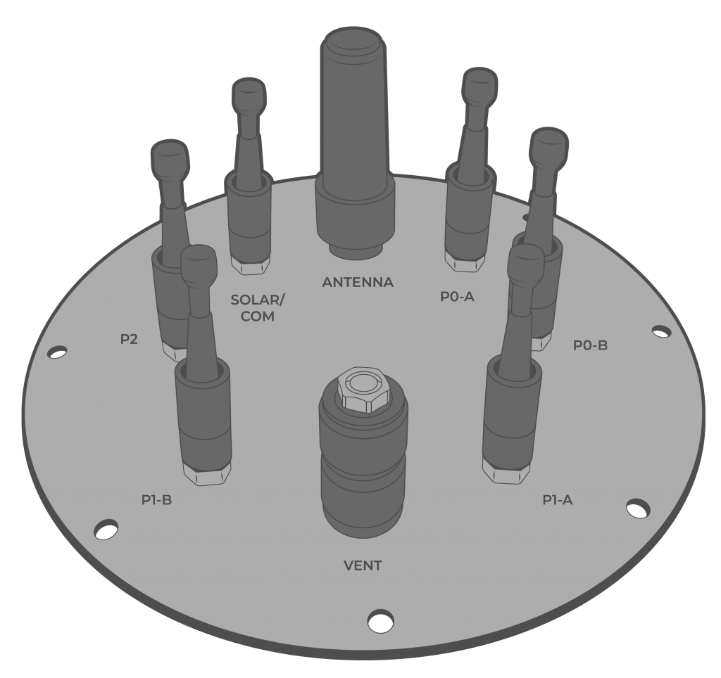
Figure 3: X2-CBMC port configuration. |
- [For CB-150/250/450 buoys only] Use a 9/16″ socket wrench to remove the (6) bolts holding the buoy’s solar tower to access the data well.
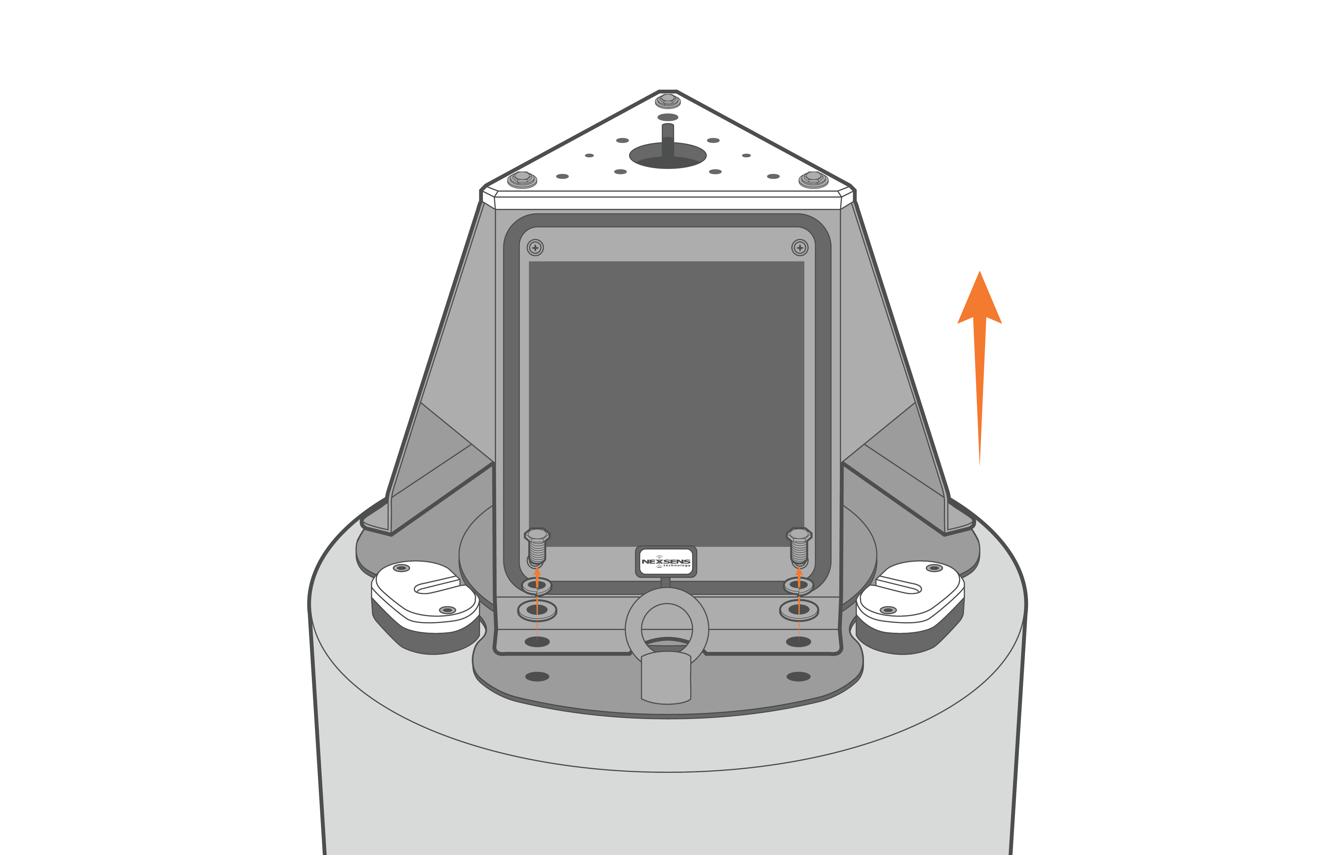
Figure 4: Remove solar tower from CB-150/250/450 buoys.
- Remove the (8) bolts from the X2-CB/X2-CBMC using a 9/16″ socket wrench.
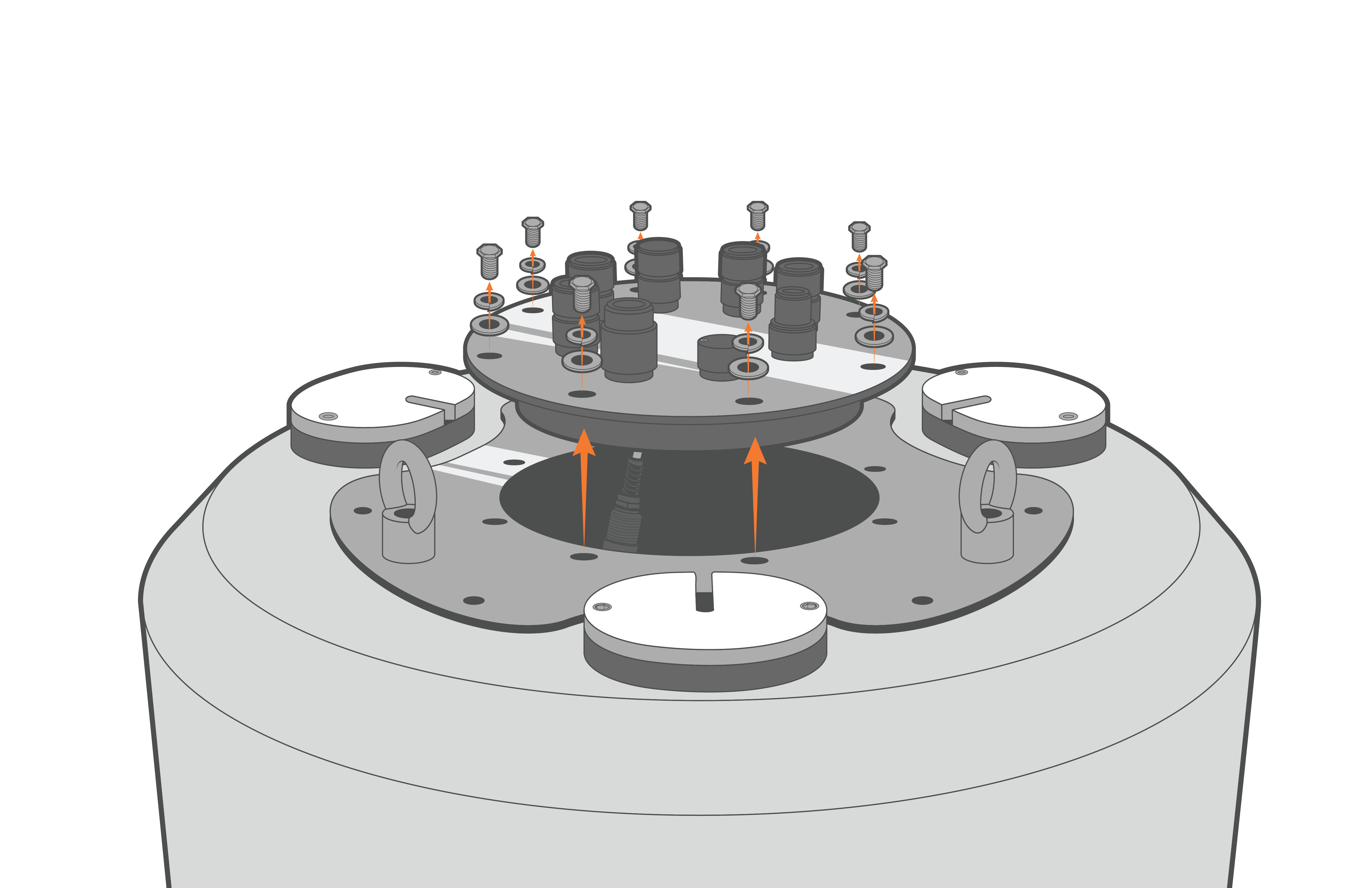
Figure 5: X2-CB removal from CB-150/250/450 buoys. |
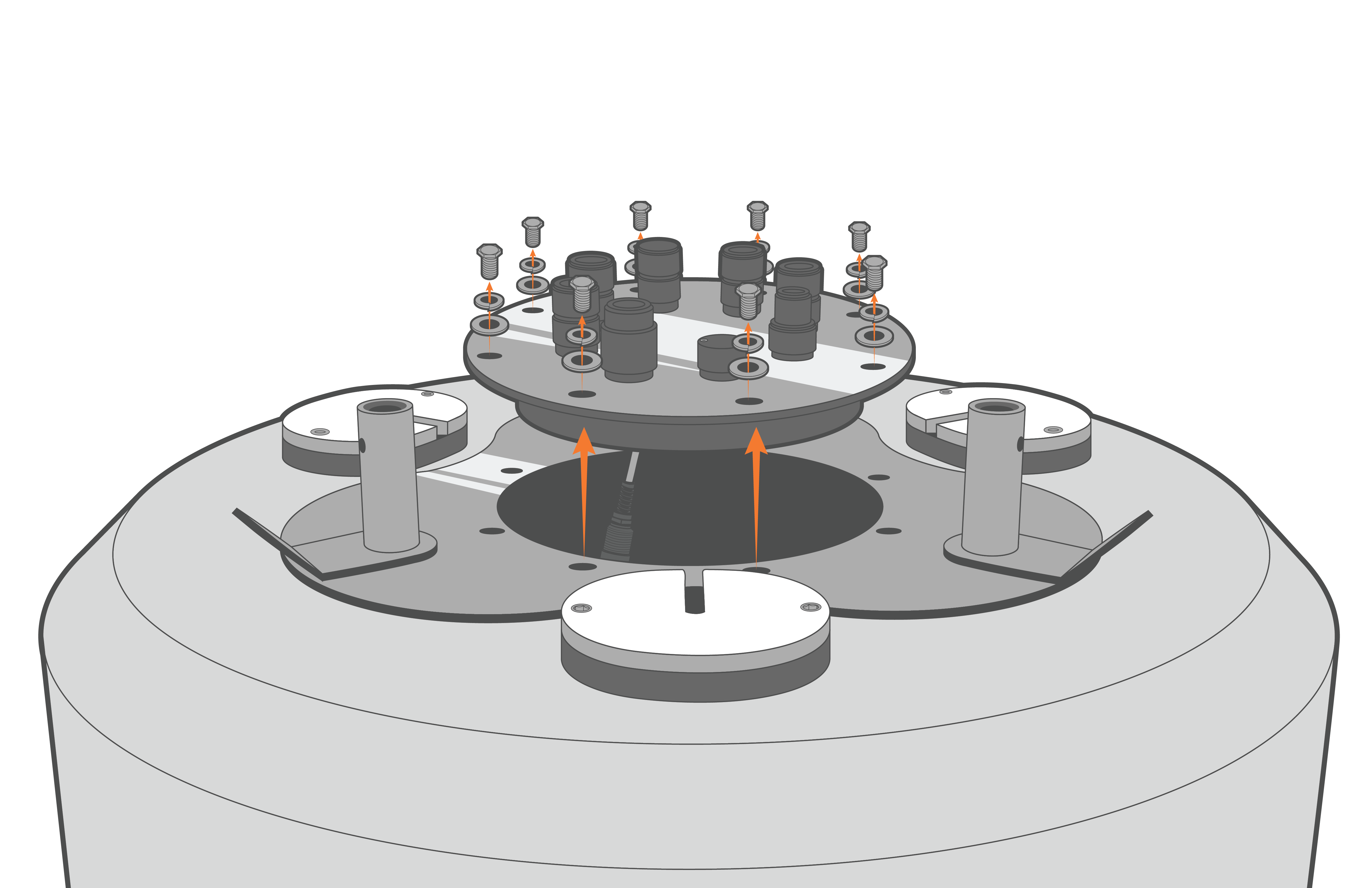
Figure 6: X2-CB removal from CB-650/950/1250 buoys. |
- Lift up the logger and then disconnect the 6-pin plug connecting the battery harness to the bottom cable of the X2 logger.

Figure 7: Unplug X2-CB in CB-150/250/450 buoys. |

Figure 8: Unplug X2-CB in CB-650/950/1250 buoys. |
- Invert the logger plate and then remove the (8) 8-32 x 1/2 screws holding the X2 enclosure to the metal plate using a Philips-head screwdriver.
- Gently lift the enclosure to expose the RTU PCB of the X2. Statically ground yourself prior to touching any of the electronics inside the X2 logger.
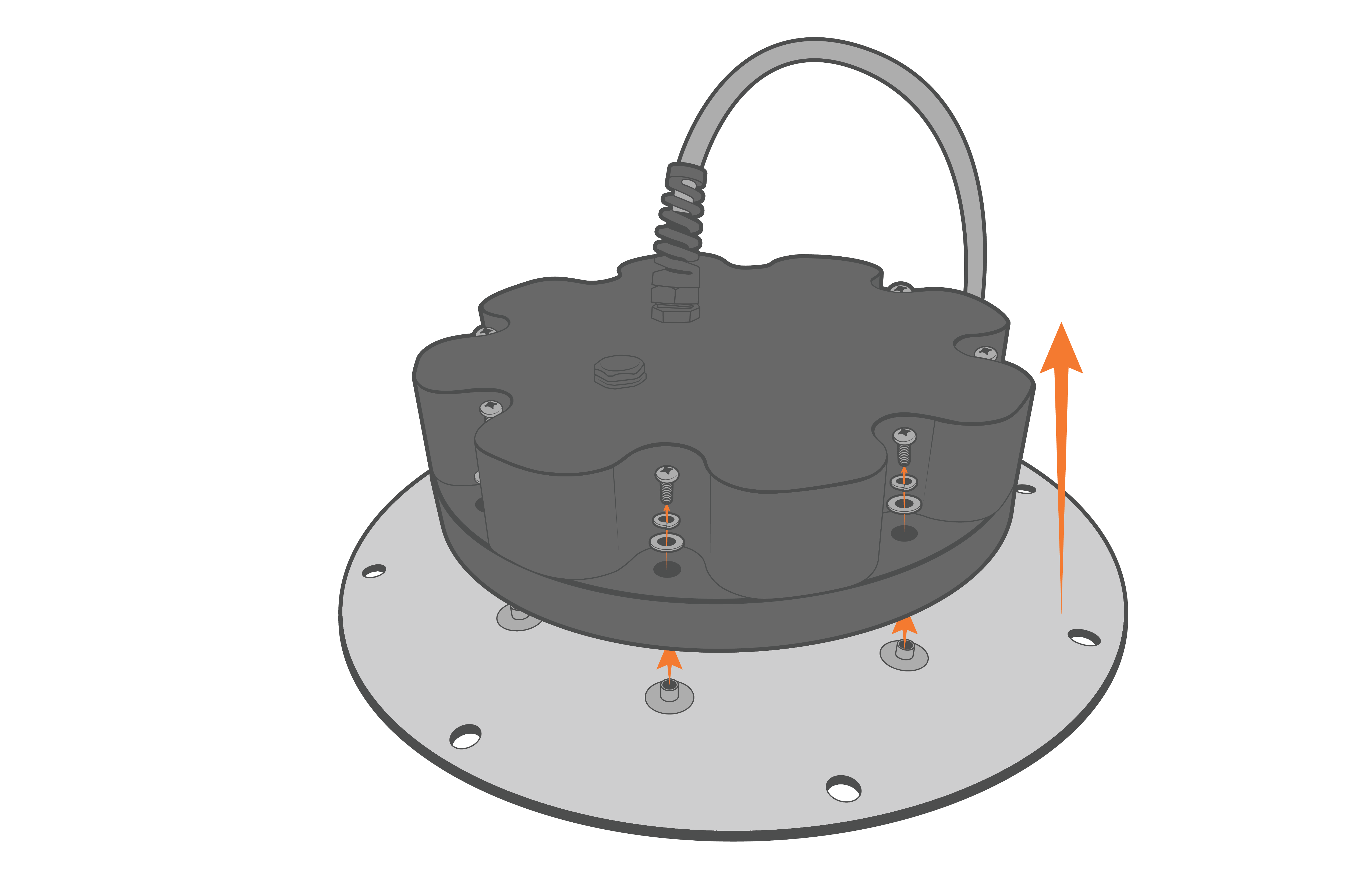
Figure 9: Remove the X2-CB/X2-CBMC housing screws.
- Disconnect the 4-pin Molex connector between the enclosure and the X2 data logger.
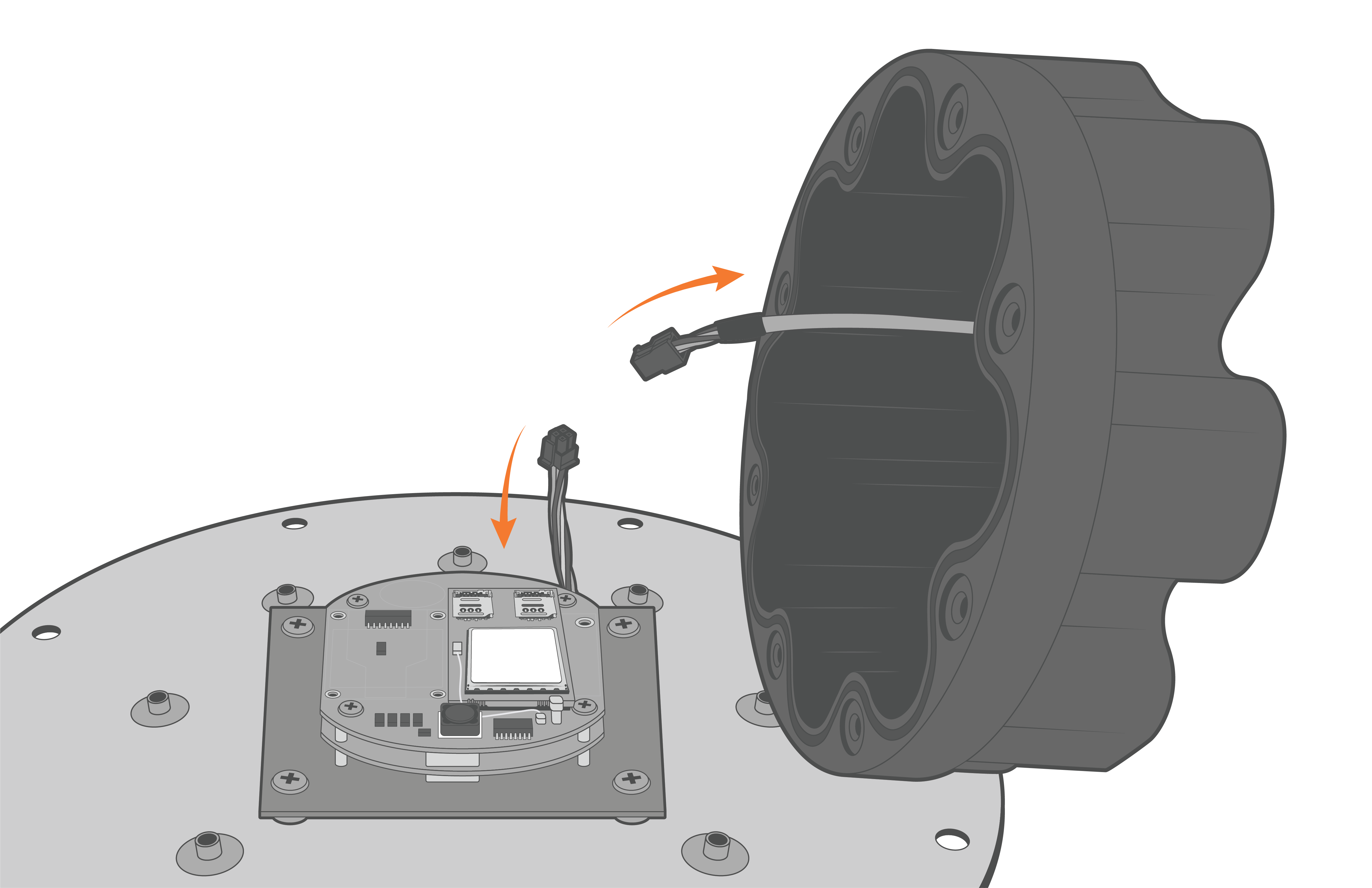
Figure 10: Disconnect the Molex power connector.
- Locate the SIM slot tray on the cell modem. NexSens provides two distinct modem models within an X2 data logger.
- Devices sold within the United States, and certain international shipments, will have an AT&T, Verizon, or NA4G modem outlined in the schematic on the left below.
- Devices sold internationally that do not support the frequency bands with the modems described above, will therefore have the CAT-M Worldwide modem outlined in the schematic on the right below.
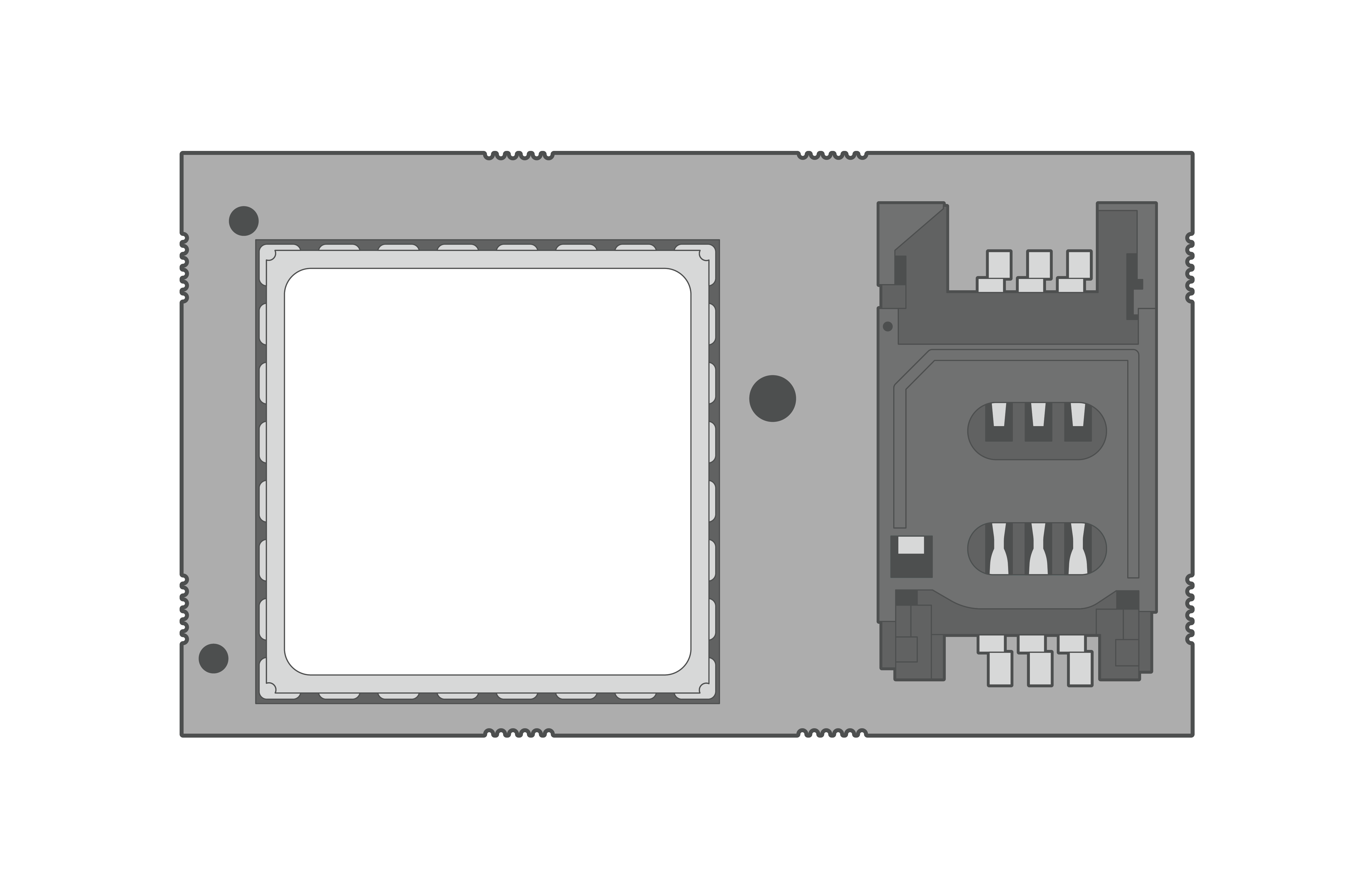
Figure 11: AT&T, Verizon, & NA4G modem schematic. |

Figure 12: CAT-M modem schematic. |
- For each modem model, orient the modems as shown below, then follow the arrows to unlock and open the SIM card tray.
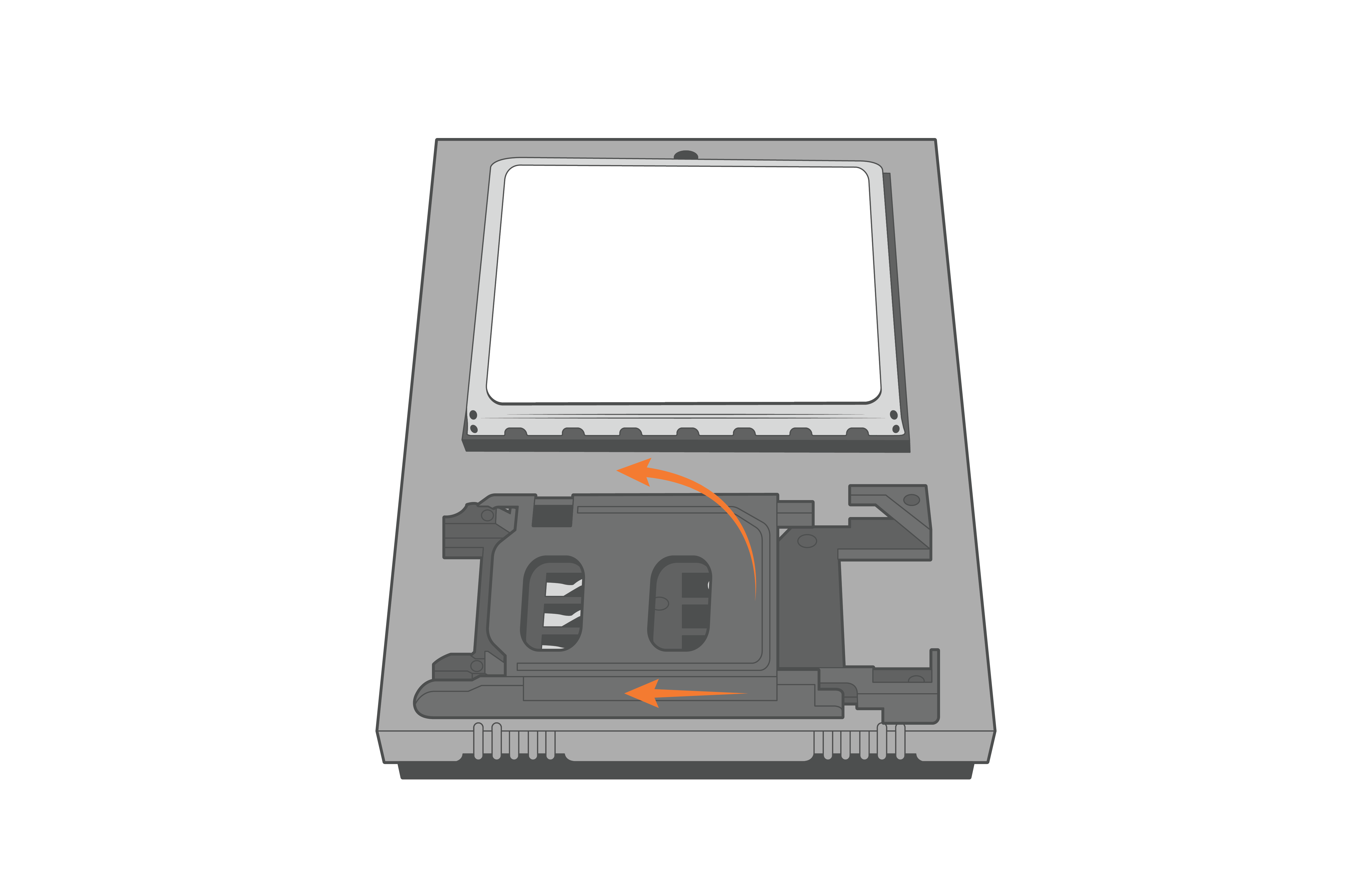
Figure 13: Open the AT&T, Verizon, or NA4G modem SIM card tray. |
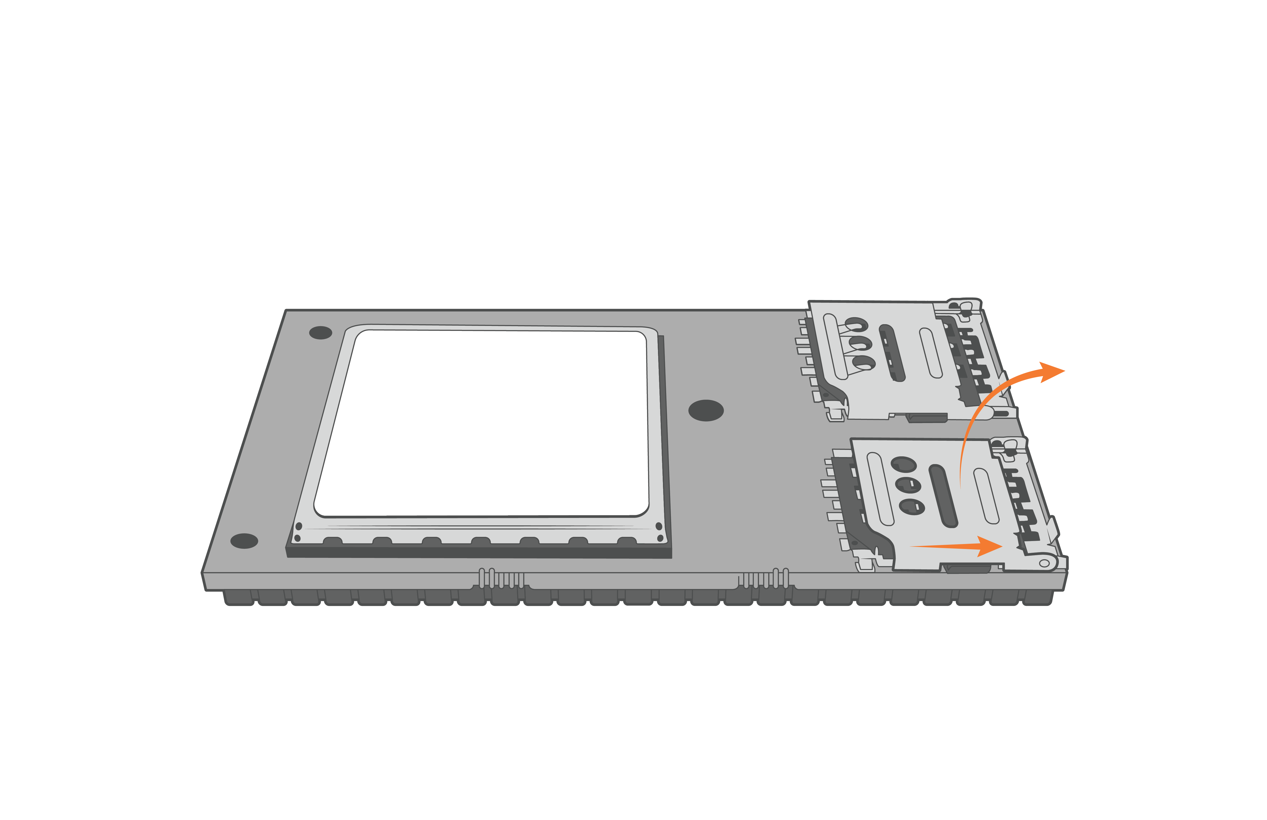
Figure 14: Open the CAT-M modem SIM card tray. |
- Slide the SIM into the tray such that the indentation on the card will align with the same indentation on the holder when closed.
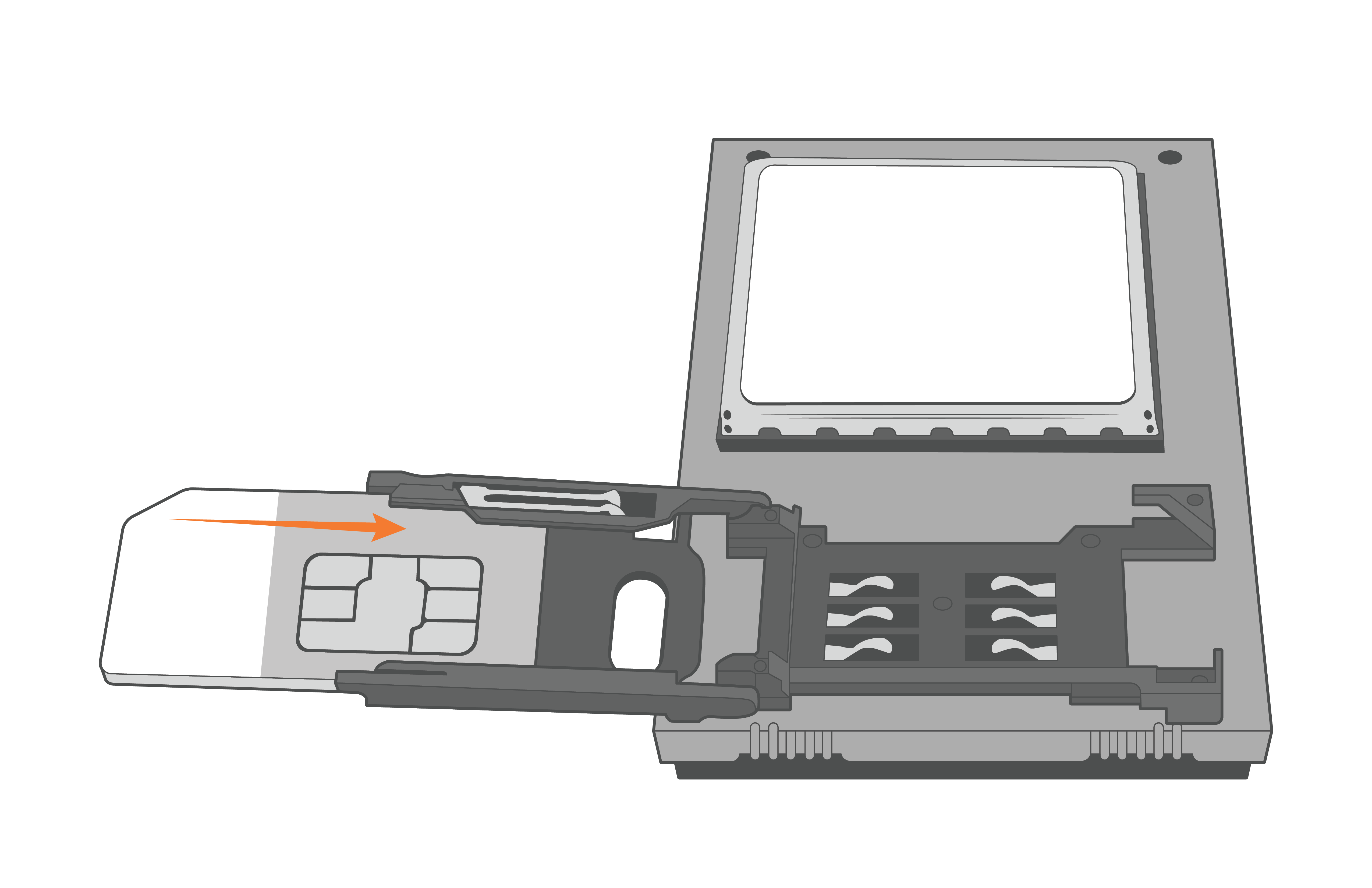
Figure 15: Insert the 2FF size (25mm x 15mm) SIM card into the AT&T, Verizon, or NA4G modem. |
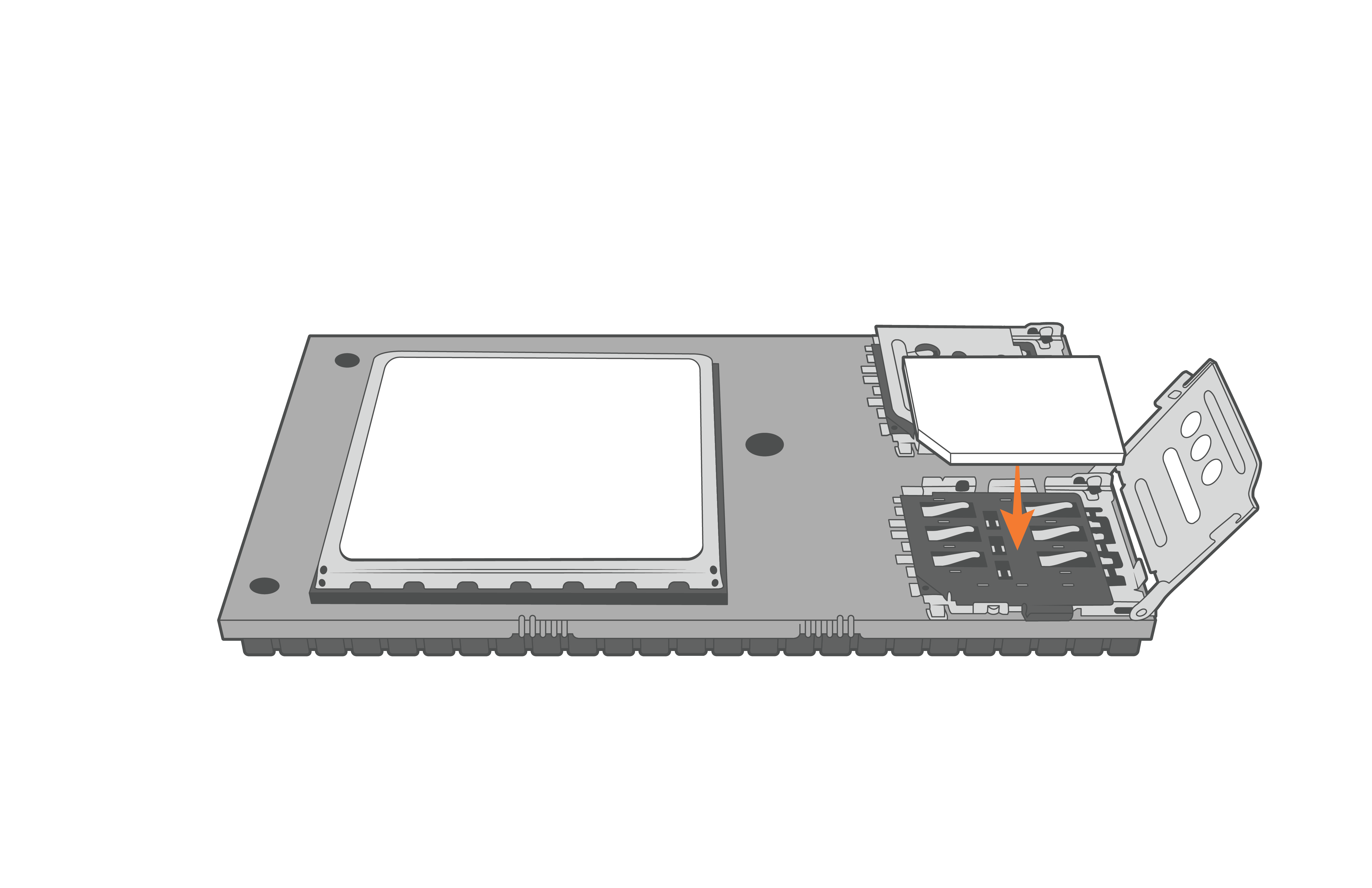
Figure 16: Insert the 4FF size (12.3mm x 8.8mm) into the CAT-M modem. |
- Gently swing the tray closed and then press forward gently to lock it back into place.
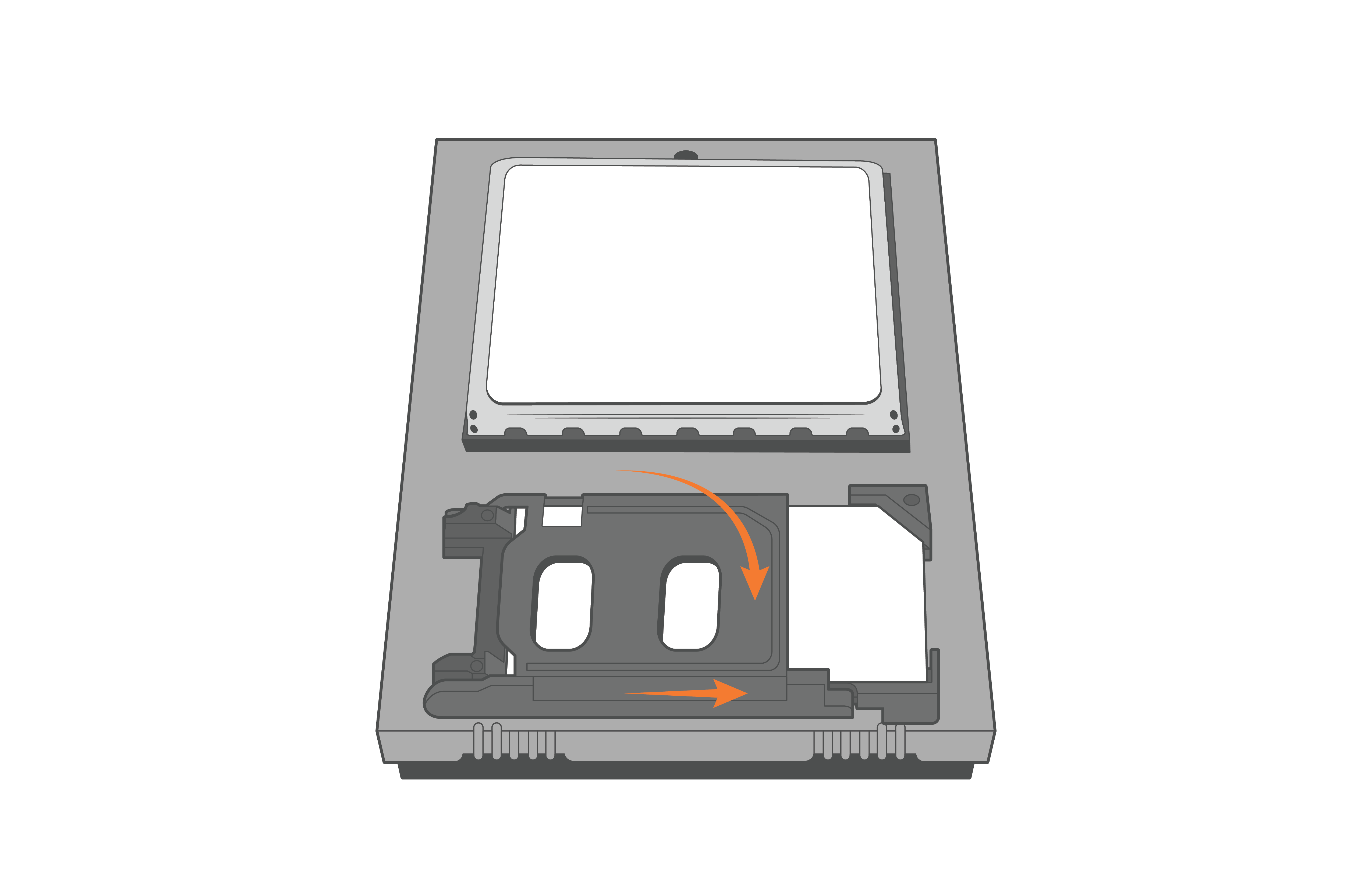
Figure 17: Close the AT&T, Verizon, or NA4G modem SIM tray. |
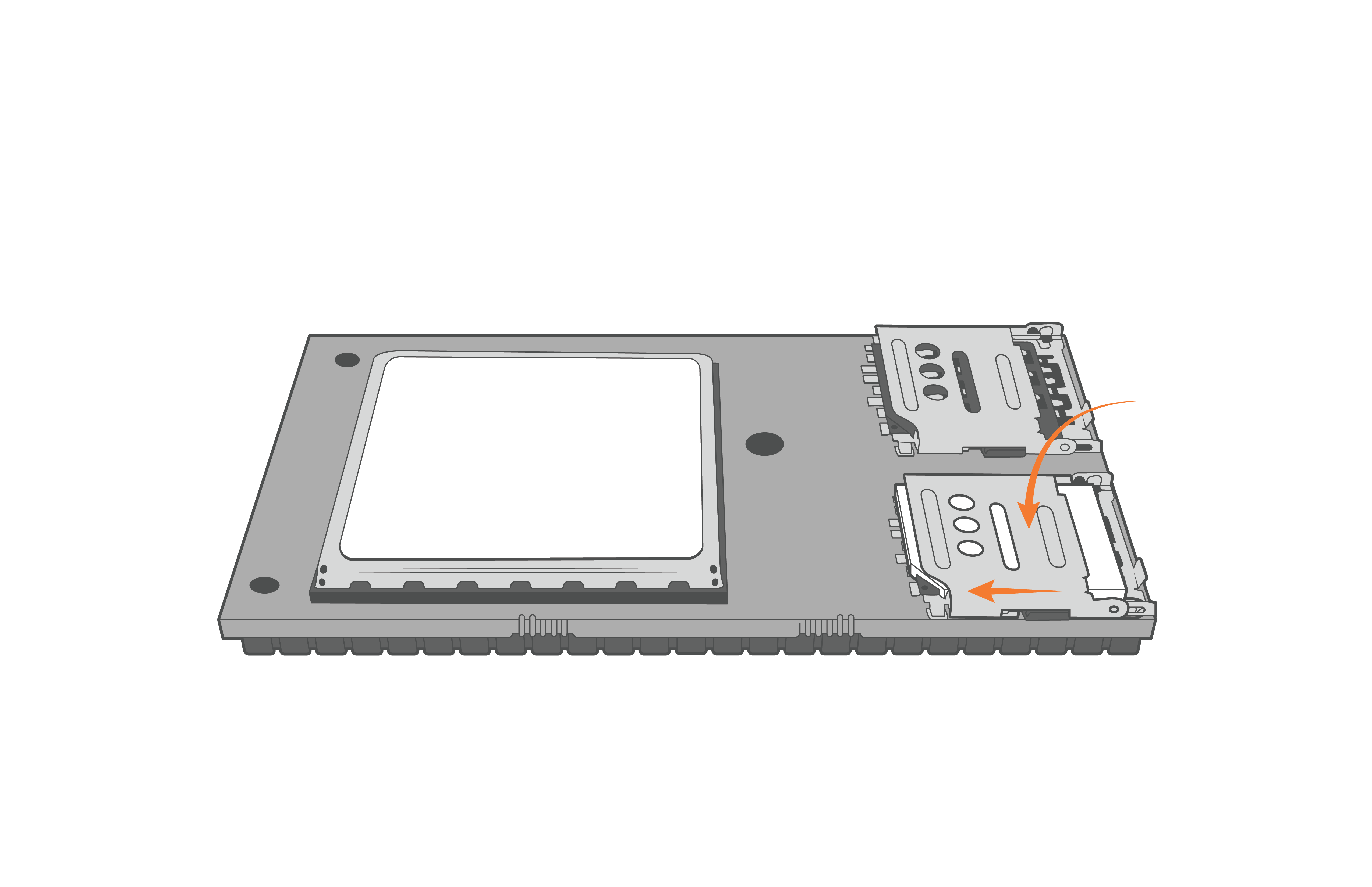
Figure 18: Close the CAT-M modem SIM tray. |
- Realign the O-ring within the grooves on the bottom of the X2-CB/X2-CBMC enclosure.
- Place the desiccant on the RTU board next to the modem.
- Orient the X2-CB/X2-CBMC enclosure such that the power cable feeding up through the bottom of the base lies flat when closed and is not above the cellular modem.
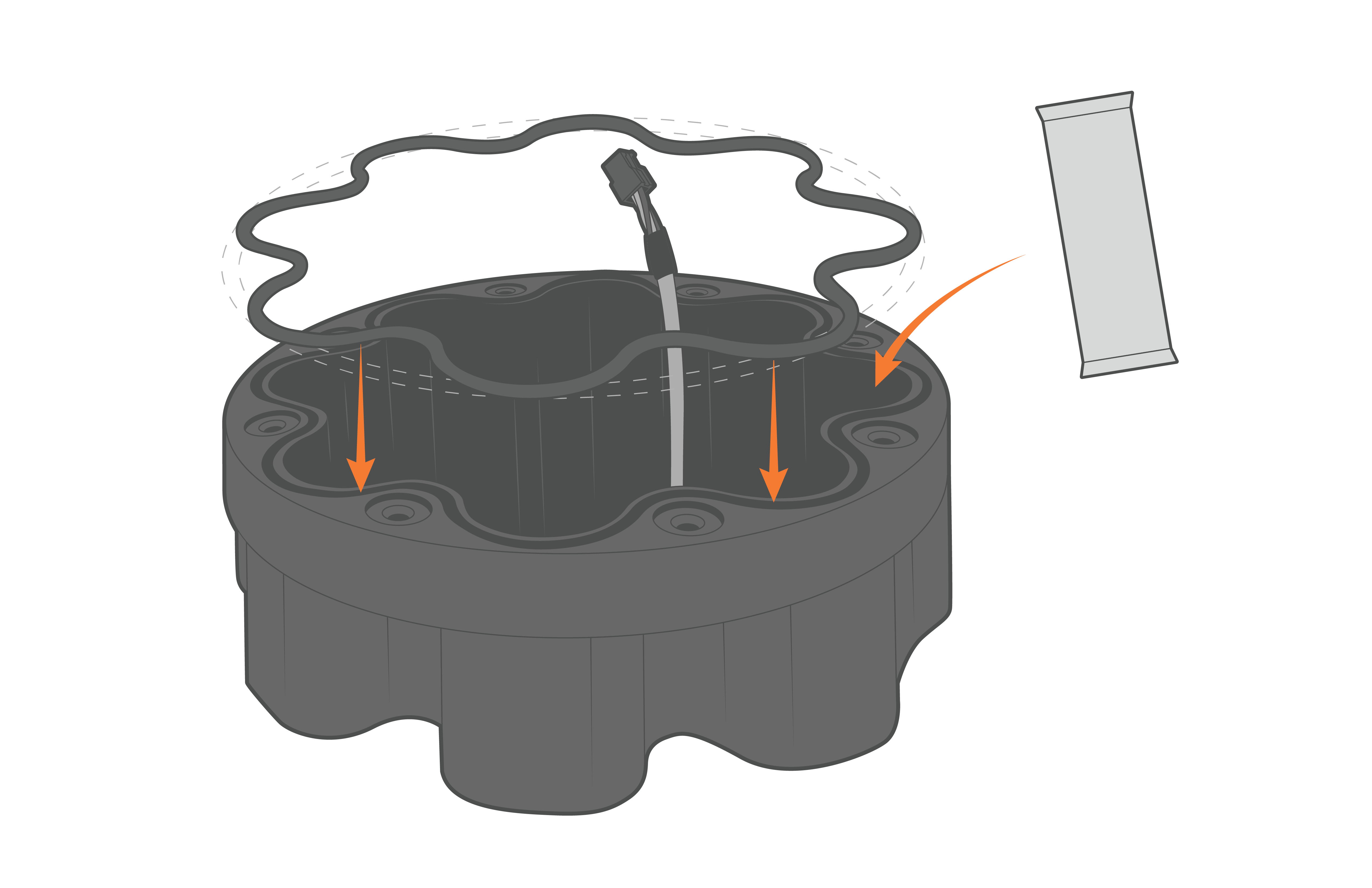
Figure 19: Re-align the O-ring and ensure to replace the desiccant. |
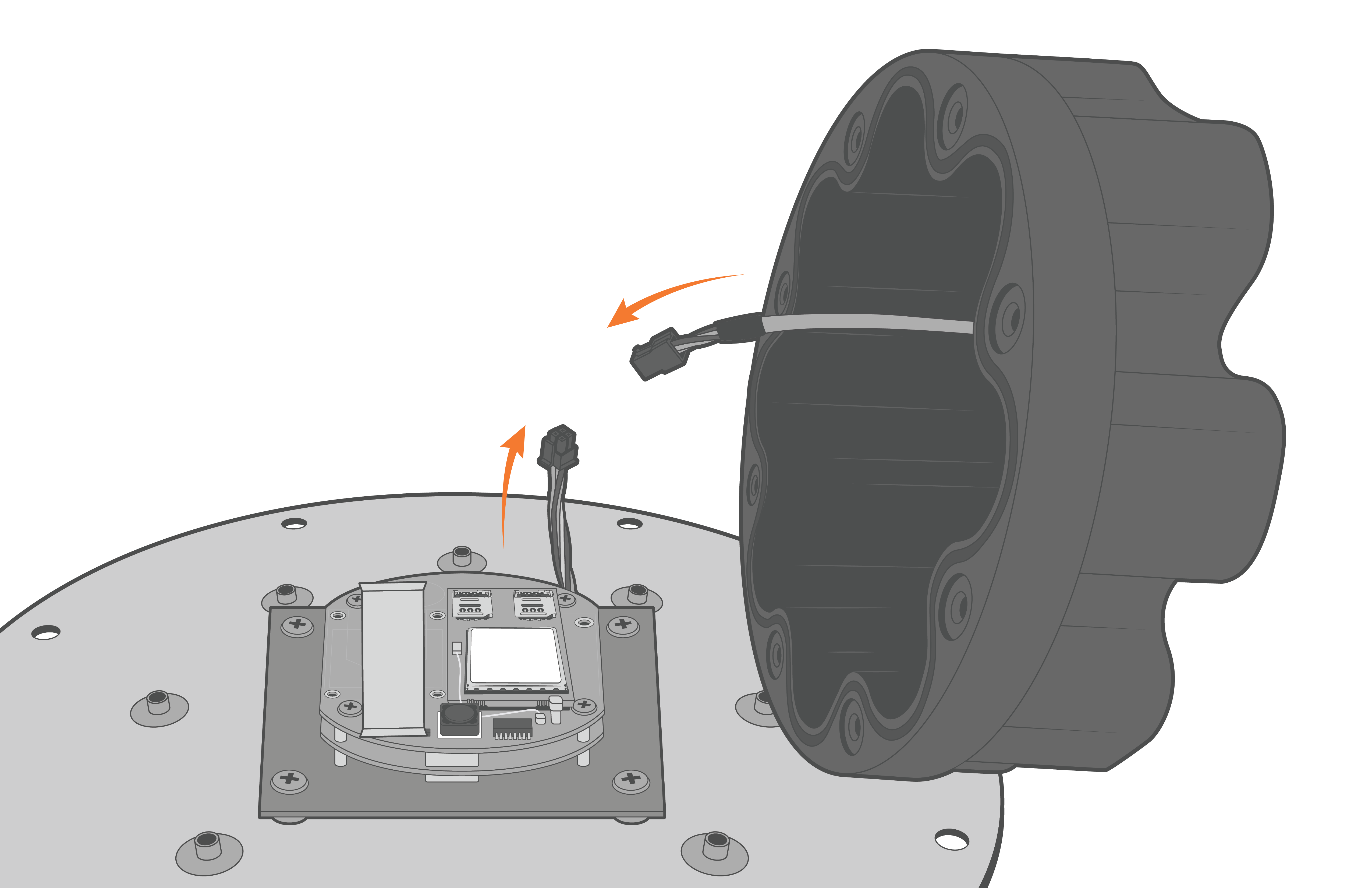
Figure 20: Reconnect the Molex power cable. |
- Align the holes on the enclosure with the threads on the plate accordingly. Ensure the large exterior O-ring is secure in its grooves and is making proper contact with the bottom of the logger plate.
- Thread the (8) 8-32 x 1/2 screws in halfway, before tightening in a cross pattern with a Phillips Screwdriver.
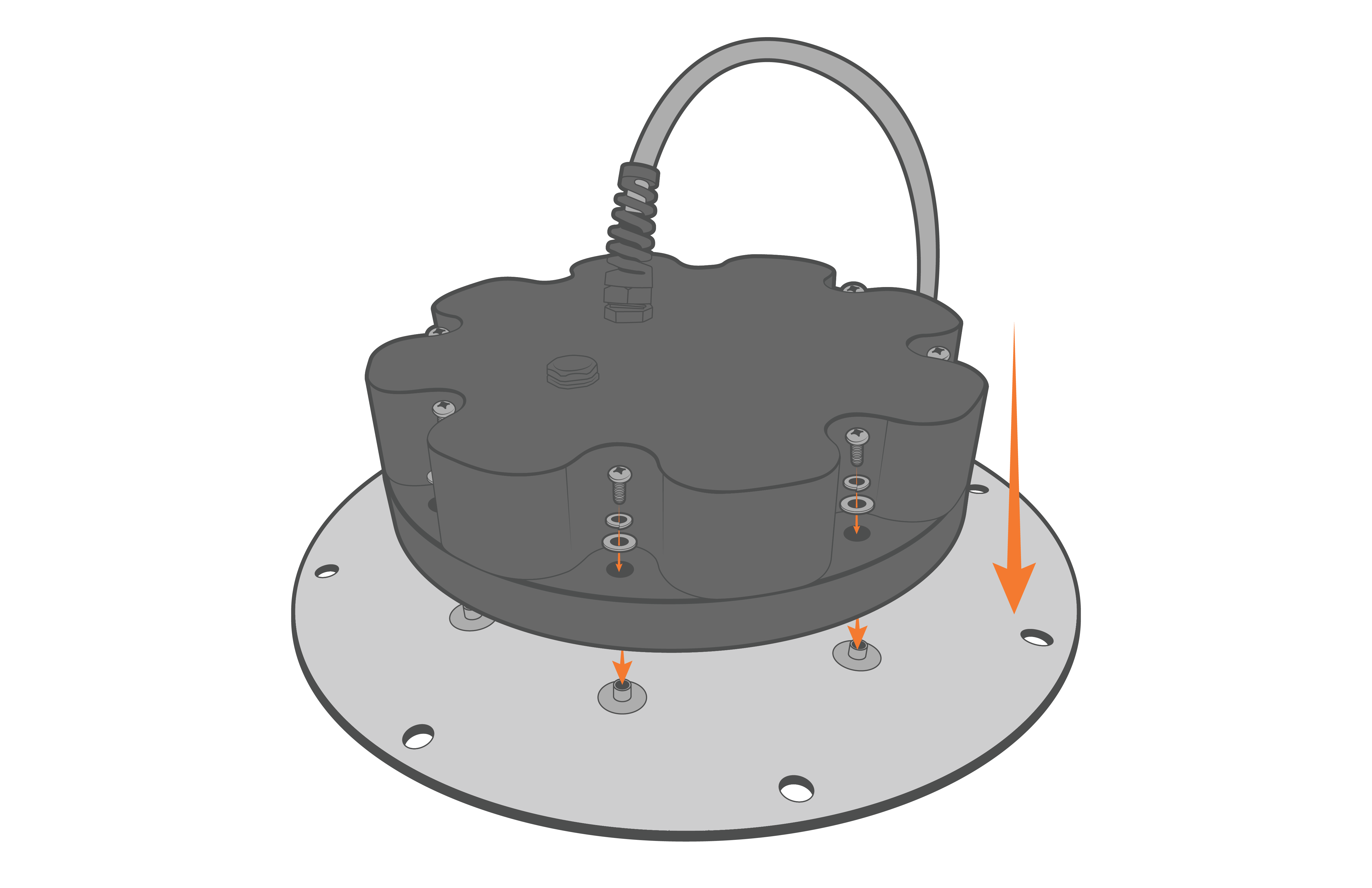
Figure 21: Re-install the X2-CB-X2-CBMC enclosure. |
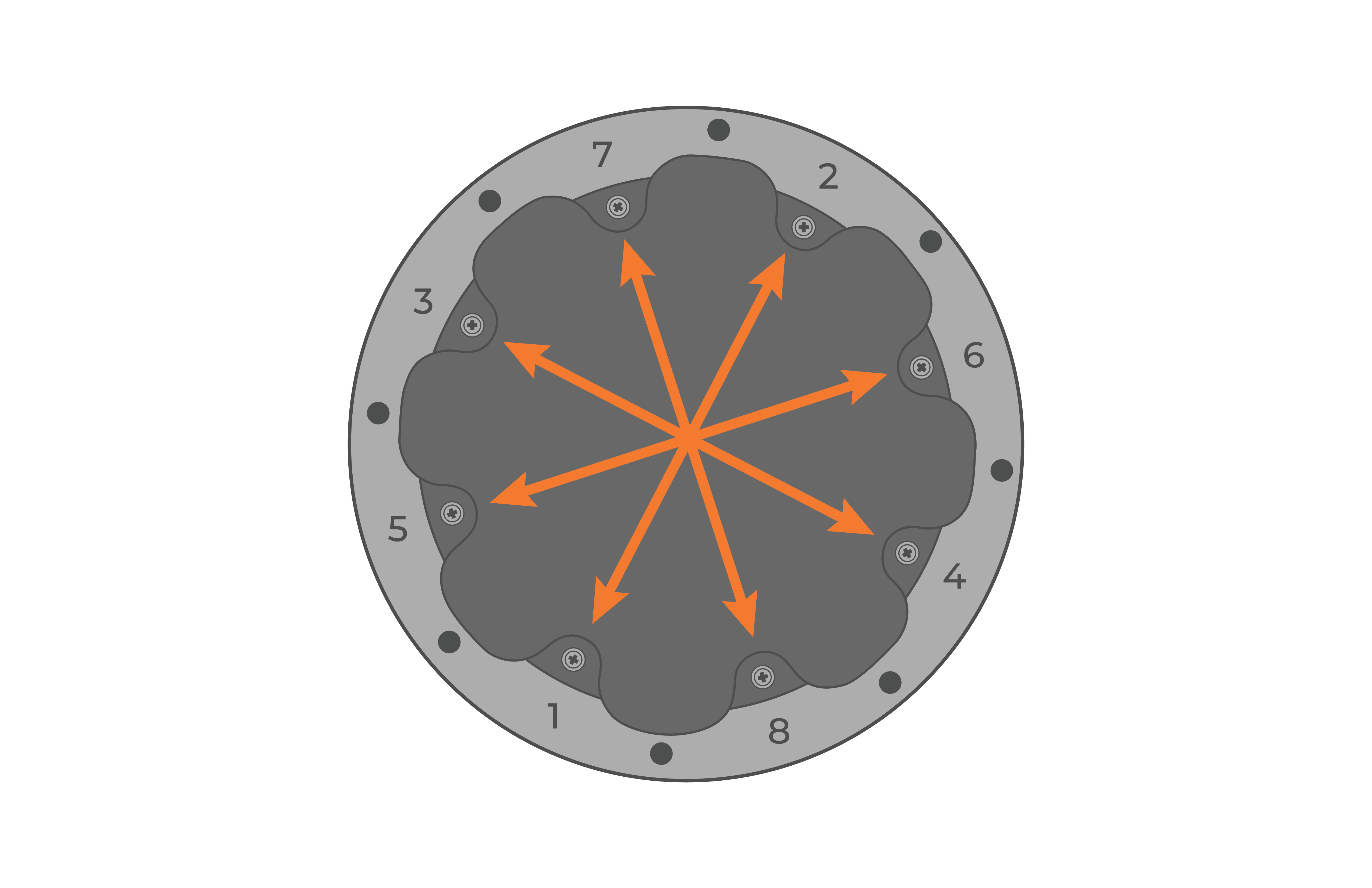
Figure 22: Evenly tighten the screws in a crisscross pattern |
- Power on the logger using a UW6-USB-485P cable and open the CONNECT software. Use the article link below to ensure the SIM card is read successfully in the software and set up the cellular network.
- Set up the cellular connection on an X2 Data Logger Using CONNECT
- If the SIM card ID is not read, open the logger enclosure and re-position the SIM card.
- Set up the cellular connection on an X2 Data Logger Using CONNECT
- Place the re-assembled X2-CB/X2-CBMC back on top of the data well.
- Make sure the primary O-ring is clear of debris and centered in the groove.
- It is recommended to replace the desiccant pack within the data well at this time.
- Reconnect the 6-pin plug on the bottom cable of the X2 logger to the battery harness cable.
- Make sure the primary O-ring is clear of debris and centered in the groove.
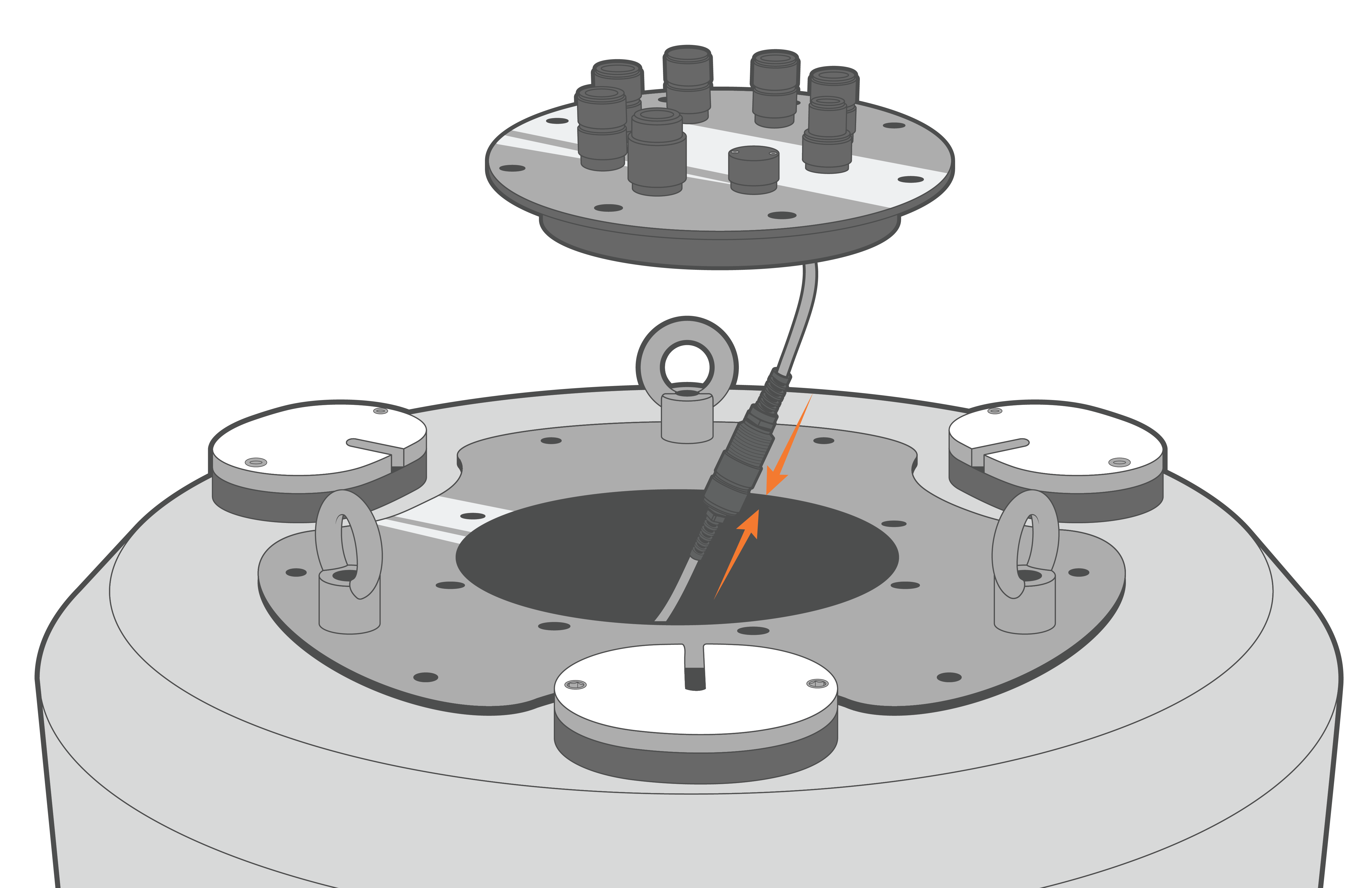
Figure 23: Re-connect the data well 6-pin cable connection.
- Align the plate and re-install the (8) bolts with lock washers, tightening them in a cross-pattern using a 9/16″ socket wrench.
- Orient the SOLAR/COM port towards one of the deployment tubes for easier access when the solar tower is installed.
- Ensure there are no substantial gaps between the data logger plate and the metal frame of the buoy data well.
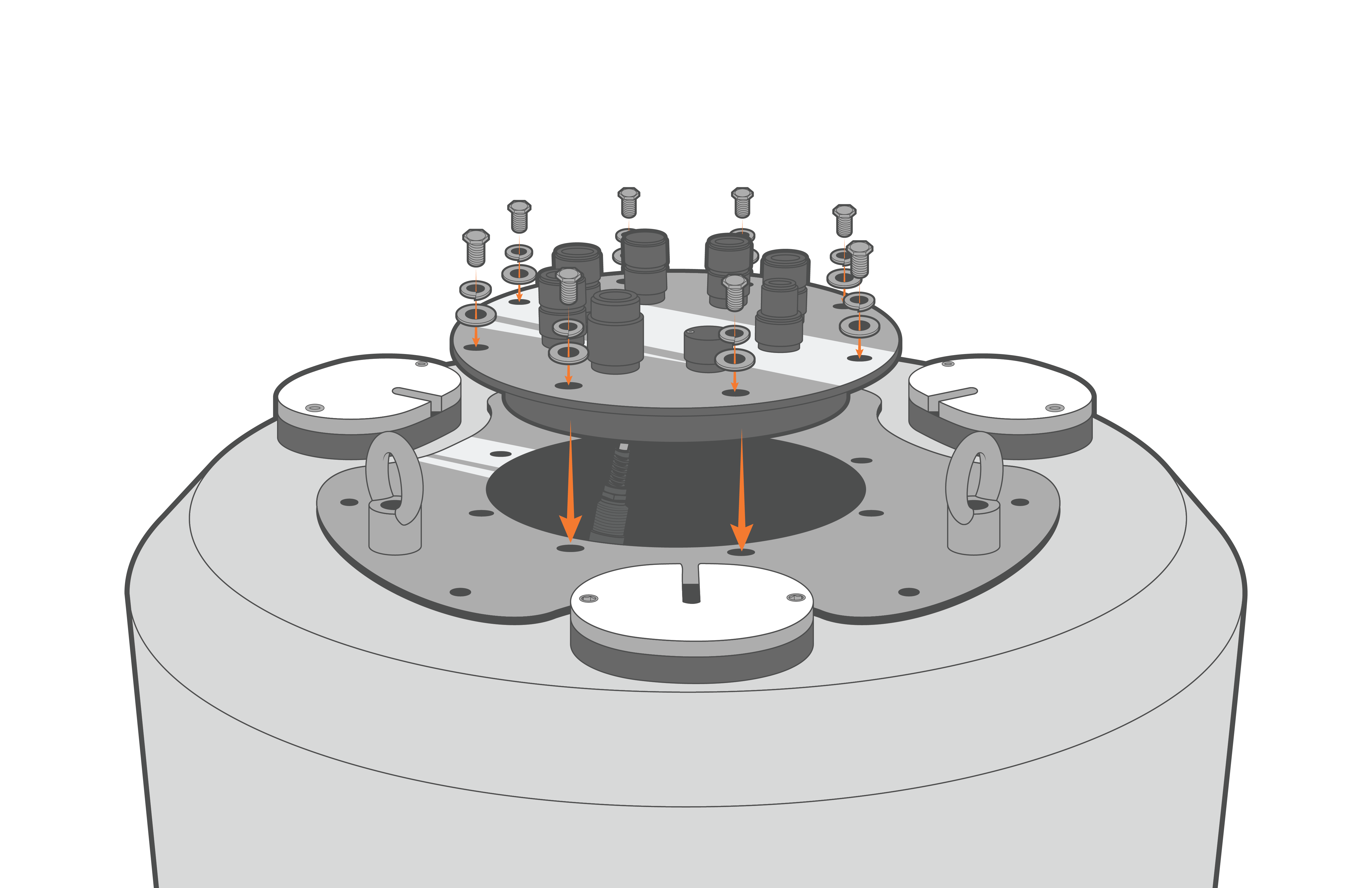
Figure 24: Bolt down the X2-CB/X2-CBMC. |
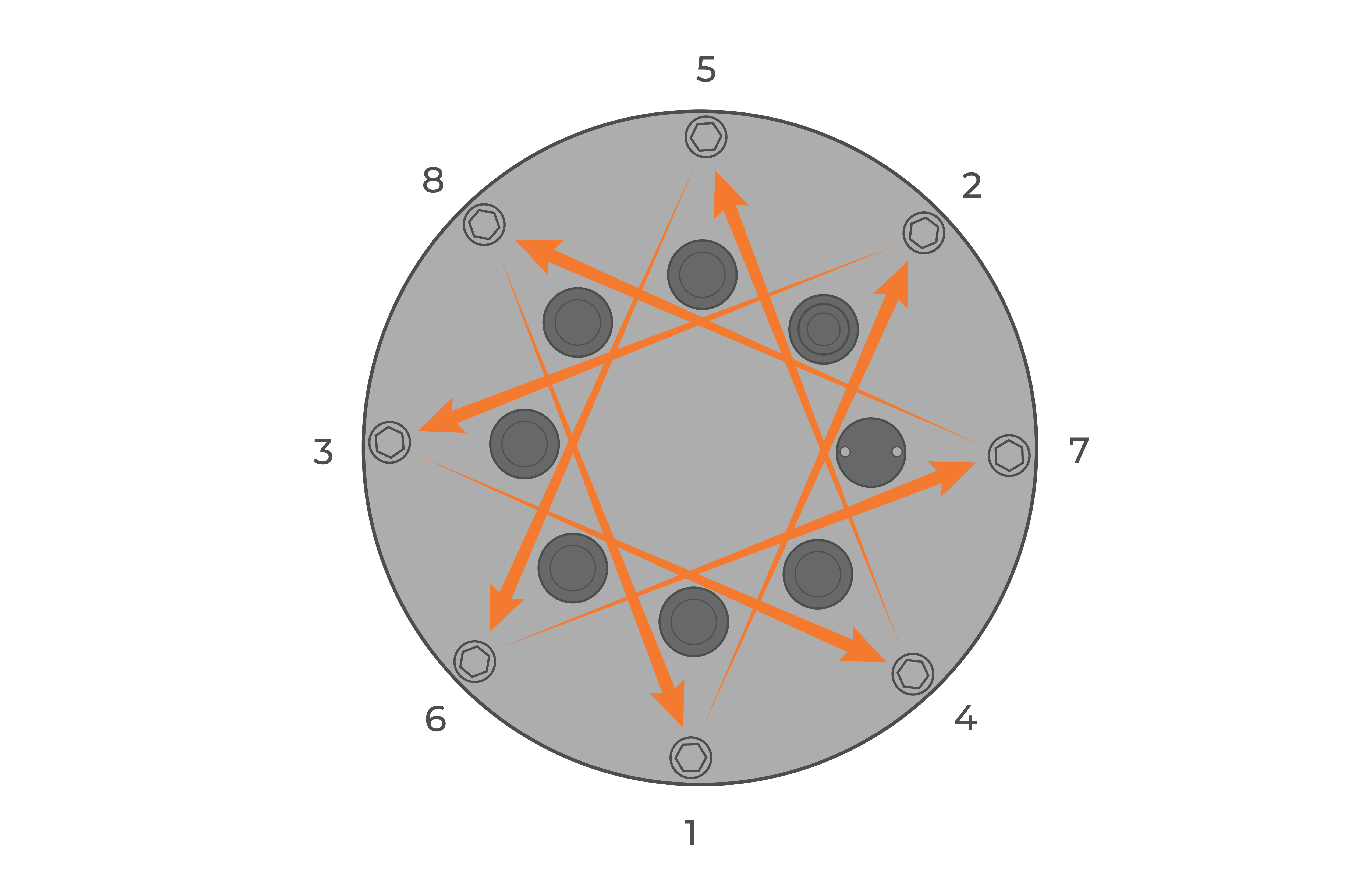
Figure 25: Bolt down the logger in a crisscross pattern. |
- Re-install the solar tower and move the buoy outside. Power on the logger using the solar tower plug and gather multiple hours of readings to ensure the primary power is increasing while the buoy is in direct sunlight.